Clamping parameters and 48 V rail fit
The 1.5SMC62CA: At 58.9 V minimum breakdown, the device enters conduction and begins clamping. Peak pulse power is 1500 W at the 10/1000 µs surge shape — the industry-standard TVS test waveform representing an inductive kick or mains transient. The 17.9 A peak pulse rating at that waveform confirms the device survives a single-event surge of that magnitude without going into thermal runaway.
Junction temperature and thermal margin
Rated junction temperature runs to 150 °C — the upper bound is set by the die attach and mold compound, not the Zener junction itself. In a still-air enclosed panel, the SMC package thermal resistance to ambient typically runs 60–80 °C/W, so at the 1500 W peak pulse the junction delta is substantial but brief. For continuous clamping duty, derate per the datasheet curves; the 150 °C ceiling gives some headroom before the thermal limit drives the design.
DO-214AB package and board integration
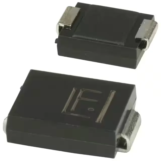
Surface-mount DO-214AB (SMCJ supplier package) — the cathode bar straddles a large thermal pad on the PCB. Layout matters: the pad area under the cathode directly sets thermal impedance to the board, and the clamping performance under repeated surge is a function of how effectively that heat spreads. A four-layer board with solid ground plane under the SMC gives significantly better thermal performance than a two-layer design with minimal metal.
Listed as Active by Littelfuse — part of the mainstream 1.5SMC series spanning a wide voltage range from 5 V up through 440 V. The series is widely second-sourced across the industry, and the DO-214AB pinout is consistent across manufacturers, so a cross-source alternative is a straightforward check at RFQ if single-source risk on the BOM line is a concern.