What this part is — and why the clamping spec matters
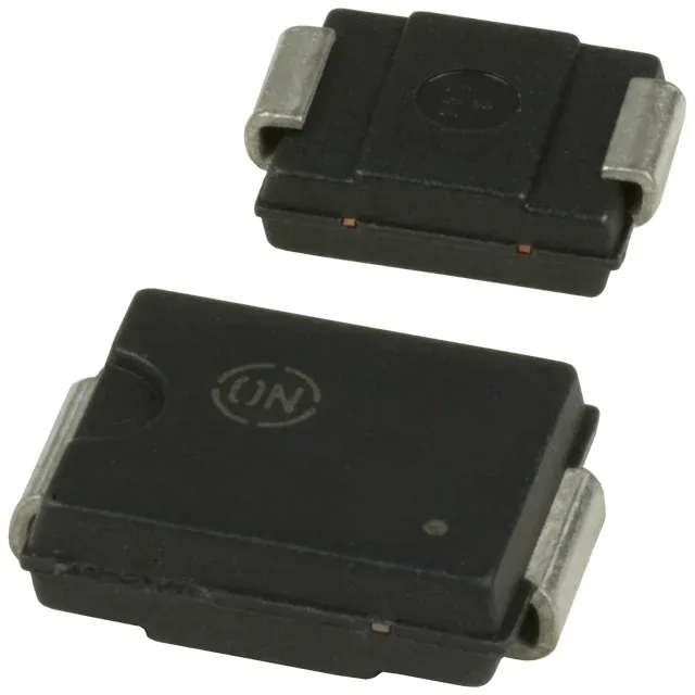
The 1.5SMC62AT3G is a unidirectional Zener-based TVS (transient voltage suppressor) in the DO-214AB (SMC) surface-mount package, from Littelfuse's 1.5SMC series. Rated 53V reverse standoff (typ), it sits above the rail it protects and below the damage threshold of the downstream circuitry. That 85V ceiling is the number the downstream IC or power stage must survive — it is the design constraint, not the standoff rating. Junction temperature range runs from -65°C to 150°C, which covers most industrial and outdoor enclosures without derating concerns at normal fault-event energy levels. Tape-and-reel and cut-tape packaging options serve both high-volume SMT placement and low-quantity rework or prototype builds. The SMC body is the standard pick-and-place compatible outline for this series.
Obsolete — sourcing path and what to know before you re-design
Littelfuse has marked the 1.5SMC62AT3G obsolete. No official successor order code appears in the available record — the series continues in other voltage variants but no direct P/N replacement is confirmed on file for this specific 62V rating. For a board already in production, independent distribution channels are the sourcing path. Lot traceability and datasheet verification against the original qualification remain the buyer's diligence steps — counterfeit-screen the markings and run a voltage-characteristic check on a bench curve tracer before committing to a production run. For a new design, the entire 1.5SMC series footprint is available in multiple voltage points — sourcing a higher-voltage or lower-voltage sibling within the same package is usually possible, but pin-to-pin compatibility within the series does not guarantee the same clamping ratio; re-run the clamping and breakdown checks in the datasheet before substituting.