Active production — still a current BOM line
The 1.5KE36CA: This is a current-production part, not a phase-out or obsolete line that would force a board spin or surplus-channel hunt.
At that test condition the device clamps at 49.9V while conducting 30.5A — the clamping voltage is the voltage the downstream silicon actually sees during a surge event. For a 30.8V nominal rail, a 49.9V clamp leaves a 19V margin above the operating voltage, which is typical for protecting 24V or 28V DC buses from transients. The 30.8V reverse standoff voltage means the TVS draws negligible leakage below that level — it does not load the protected line during normal operation. Breakdown starts at 34.2V minimum, so the device stays out of the circuit until a transient pushes the rail above that threshold.
Bidirectional — one device, both polarities
A single bidirectional channel covers both positive and negative transients, which simplifies the BOM for AC signal lines or DC rails that see reverse-polarity events. The symmetrical breakdown characteristic means the clamping voltage is the same in both directions — no need to pair two unidirectional TVS diodes back-to-back. The 175°C TJ(max) is the silicon die limit, not the ambient — derate the peak pulse power above 25°C per the datasheet curve.
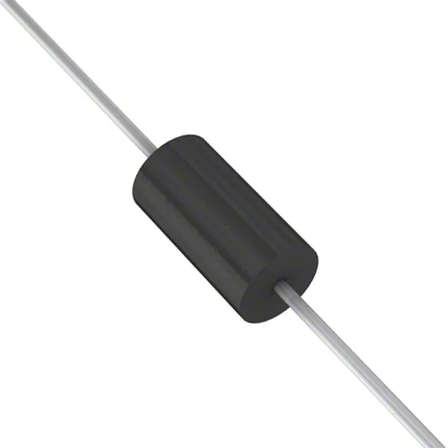
DO-201AA axial — through-hole, standard footprint
Housed in the DO-201AA (DO-27) axial-lead package, through-hole mount. The 0.040-inch (1.0mm) diameter leads suit wave-solder or hand-solder assembly. The package body is 9.1mm long — the axial form factor is a standard footprint shared across the 1.5KE series, so a board layout designed for a 1.5KE36A (unidirectional) accepts this bidirectional variant without changes. Available in both Tape & Reel (TR) and Cut Tape (CT) packaging — the reel option suits automated pick-and-place for through-hole insertion, while cut tape works for prototype builds and small-batch production.