Obsolete — sourcing reality for the 1.5KE30-B
The 25.6 V reverse standoff voltage means it starts clamping above that rail level, protecting downstream silicon from transients up to 43.47 V.
What the ratings mean for your protection design
The 25.6 V reverse standoff (working voltage) is the DC rail the diode sits across without conducting — a 24 V nominal bus with tolerance up to 25.6 V is the right fit. Above that, breakdown starts at 27 V minimum, and clamping at 43.47 V limits the spike seen by the load. The 1500 W rating is the product of clamping voltage and peak current at that pulse shape; real-world energy depends on the actual transient duration. The DO-201 axial package is through-hole — easy to hand-rework or replace on a board, though the leads need a clean solder joint to handle the pulse current without lifting a pad.
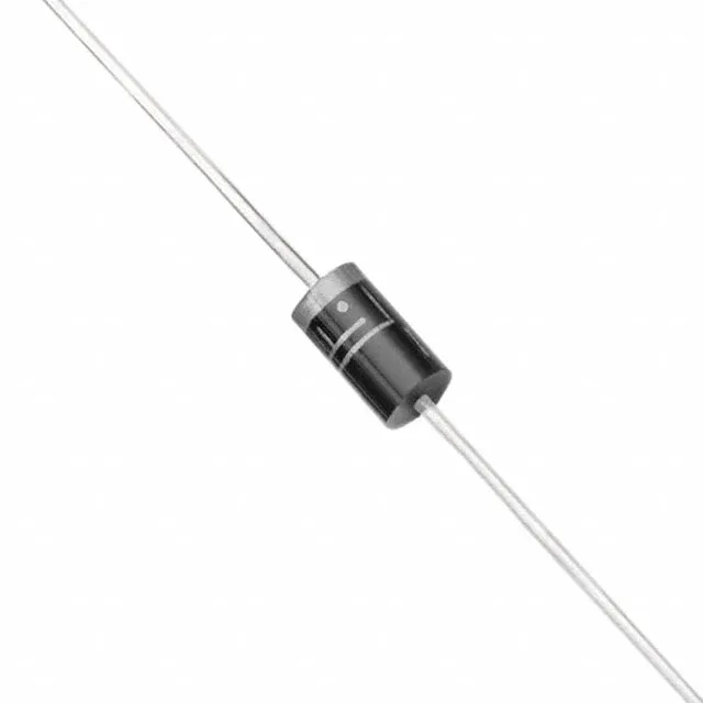
Supplied in DO-201AA (DO-27) axial leaded package, through-hole mount. The body is bulk-packed, not tape-and-reel. Polarity is marked by the cathode band — the unidirectional channel clamps only one polarity, so orientation matters on the board.