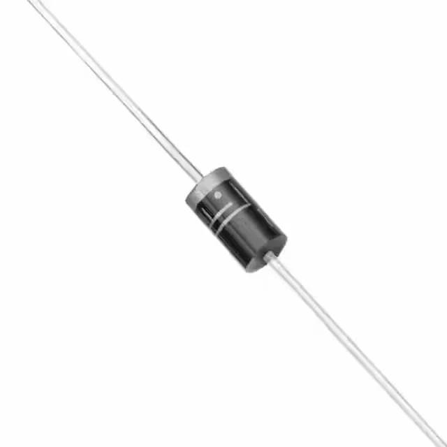
TVS diode for 94 V rail protection
The 1.5KE110C: The 94 V reverse standoff voltage (working voltage) means the diode does not conduct at the normal rail voltage, only during an overvoltage event. The minimum breakdown voltage of 99.45 V provides the trigger threshold — once the transient pushes the rail above that, the device avalanches and shunts the surge current to ground.
What the ratings mean for the circuit
For shorter pulses (e.g. 8/20 µs), the peak power capability is higher; for longer or repetitive surges, derate accordingly. The clamping voltage of 159.6 V at 10 A is the maximum voltage the protected rail sees during the surge. If the downstream circuitry (e.g. a 100 V-rated DC-DC converter input) cannot tolerate that peak, a lower-clamping TVS or additional input filtering is needed. The junction temperature derates the peak pulse power above 25°C per the standard TVS derating curve (not reproduced here).
The DO-201AA (DO-27) axial leaded package is a through-hole form factor with a 0.052-inch diameter lead. It mounts into a 0.040-inch plated through-hole on the PCB. The axial leads are typically bent to a 0.400-inch lead spacing for insertion. The tape and reel packaging is suitable for automated insertion but the part is obsolete, so reel quantities are limited to available surplus lots.