Infineon lists the TLE9877QTW40XUMA1 as Active. No end-of-life notice or last-time-buy schedule is in force.
40 MHz Cortex-M0 with automotive voltage range
The ARM Cortex-M0 core runs at 40 MHz — enough throughput for a sensorless field-oriented control loop on a BLDC motor, with margin for the commutation and current-regulation tasks. The 32-bit single-core architecture keeps the firmware porting path simple if the design already uses Cortex-M0. Supply voltage spans 5.5 V to 27 V — this covers the full automotive battery range: a cold-crank dip to 6 V and a load-dump transient up to 27 V are both within the operating envelope, so no external pre-regulator is needed for the MCU rail. Junction temperature rating of -40°C to 175°C qualifies the die for under-hood and engine-bay deployment. The 175°C ceiling is above the standard AEC-Q100 Grade 0 limit (150°C), meaning this part can sit on the engine block or near the exhaust manifold without derating.
On-chip memory map for motor-control firmware
64 KB flash plus 6 KB RAM plus 4 KB EEPROM fits a typical BLDC motor-control stack: the Hall-sensor or sensorless commutation routine, the PI current loops, and the LIN communication layer. The EEPROM block stores calibration constants and fault logs without needing an external serial EEPROM. Program memory is FLASH type — in-system reprogrammable via the UART or LIN bootloader, so firmware updates in the field are feasible without a debug probe.
Peripheral set and connectivity
Connectivity covers LINbus, SPI, SSC, and UART/USART — LIN is the standard body-control bus in automotive; SPI and SSC talk to external sensor hubs or a companion CAN transceiver. 10 general-purpose I/O are available for switch sensing, LED drive, or fault output.
48-TQFP exposed-pad — board-fit note
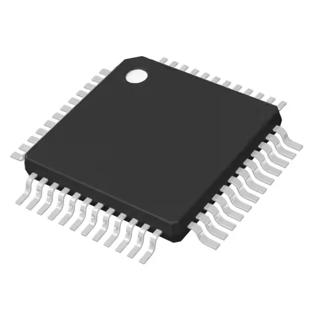
The 48-TQFP Exposed Pad package measures 7x7 mm. Surface-mount mounting with the internal oscillator means the only external timing component is the crystal or resonator if the application needs tighter accuracy than the internal RC provides — for LIN communication the internal oscillator is usually sufficient.