Half-bridge driver with 200V bootstrap — 600mA sink drives the gate hard
The IRS2001PBF-INF is a half-bridge gate driver from Infineon designed to drive IGBTs and N-channel MOSFETs in a half-bridge configuration. It integrates a bootstrap diode rated to 200V on the high side, so you can drive the top FET without a separate isolated supply — common in motor-drive inverters, UPS systems, and switch-mode power supplies. Peak output current is 290 mA source and 600 mA sink. That 2:1 sink-to-source ratio means the driver pulls the gate down fast during turn-off, reducing Miller-plateau dwell time and crossover conduction loss in the half-bridge. For a typical 10 nC gate charge IGBT, the 600 mA sink discharges the gate in about 17 ns — fast enough for 50-100 kHz switching without excessive ringing if the layout keeps the gate loop tight. Rise and fall times are 70 ns and 35 ns typical respectively. The 35 ns fall time is the one that matters for switching loss — the faster the fall, the less time the FET spends in the linear region during turn-off.
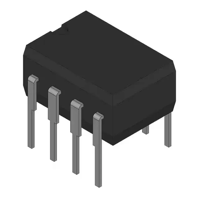
Through-hole 8-DIP — legacy board compatibility, easy rework
Packaged in an 8-pin DIP with 0.300-inch body width and 7.62 mm lead pitch. Through-hole mounting means the part sits on the board with the leads through plated holes — no fine-pitch soldering, no X-ray inspection. For a rework lab or prototype run, this is the easiest package to swap without damaging the board. Bulk packaging — tubes or trays, not tape-and-reel. If your pick-and-place feeder is set up for tape, factor in a tube feeder or hand-place this one. For low-volume builds or manual assembly, bulk is fine.
Supply range 10-20 V, logic thresholds 0.8/2.5 V
Supply voltage range is 10 V to 20 V. The 10 V minimum means it works with standard 12 V bias rails common in industrial control; the 20 V maximum covers 15 V rails with margin. Input type is non-inverting with independent channels. Each channel has its own input pin — no cross-coupling or dead-time generation inside the driver. The dead time must be handled in the PWM controller or firmware. Independent channels also let you use one driver as two low-side drivers if you don't need the half-bootstrap feature.
The 125°C TJ max means the die itself can run hot; the limiting factor in a through-hole DIP is the package thermal resistance, so ensure adequate airflow or heatsinking if the driver is switching at high frequency near the 125°C limit. ROHS3 compliant (no exemptions), so it ships into EU markets without restriction. No official successor or second-source cross-reference is documented for this order code.