Gate drive and switching behaviour — the logic-level advantage
The drive voltage range is specified from 4.5 V (minimum for the lowest Rds(on)) to 10 V (where the 13.5 mOhm figure is guaranteed). The maximum gate threshold is 3 V at 250 µA drain current, which means a 3.3 V logic output can reliably turn the FET on, though the on-resistance will be higher than the 10 V rating. Gate charge is 36 nC at 5 V Vgs, and input capacitance is 1620 pF at 25 V Vds — moderate numbers that keep switching losses manageable in the 10 kHz to 100 kHz range. For a 3.3 V driven design, verify the actual Rds(on) at 3.3 V Vgs from the typical curves; the 4.5 V minimum drive spec is a safe starting point.
Package and mounting — TO-220-3 through-hole
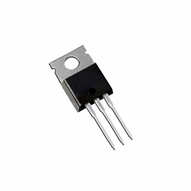
Housed in a standard TO-220-3 (TO-220AB) through-hole package, the IRLZ44Z is intended for PCB mounting with the metal tab either soldered to a copper plane or bolted to a heatsink. The tab is electrically connected to the drain. Maximum power dissipation is 80 W at case temperature, so a heatsink is required for any continuous current above a few amps. The through-hole format suits prototyping, rework, and designs where vibration resistance is less critical than thermal mass.
Lifecycle status — obsolete, sourced to order
For new designs, a current-production logic-level N-channel MOSFET in TO-220 with similar voltage and current ratings should be selected.