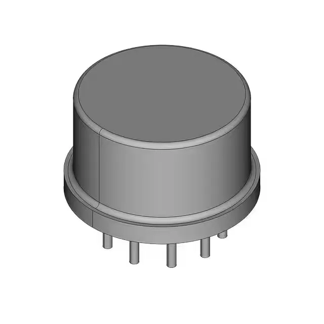
What the 1.4 mOhm Rds(on) buys you in a 25 V DirectFET
The IRF6797MTRPBF: The headline number here is the 1.4 mOhm max on-resistance measured at 38 A with a 10 V gate drive.
Gate drive and switching loss — the 68 nC number that matters
Total gate charge is 68 nC at 4.5 V, which is the figure a designer uses to size the gate-drive circuit. A 4.5 V drive is comfortably above the 2.35 V max threshold, so a 5 V logic signal from a microcontroller or a gate-driver IC turns the FET fully on. The 68 nC Qg means the driver needs to source and sink that charge each switching cycle; at 500 kHz the average gate current is 34 mA, well within a standard driver's capability. The ±20 V Vgs rating gives headroom for ringing on the gate node — a common failure mode in hard-switching converters where the Miller plateau couples a voltage spike back onto the gate. That 20 V ceiling means the part survives moderate overshoot without needing a clamp Zener on the gate.
Thermal reality for a DirectFET in a confined power supply
The DirectFET package dissipates heat through the top-side can, not a bottom-side pad — the PCB layout needs a copper plane on the top layer to pull heat off the can, and the 2.8 W power dissipation figure assumes that plane is present. Without it the junction temperature rises fast under continuous load. The 0.0058 µF output capacitance (Coss) is low for a 25 V FET at this current rating, which helps in resonant or ZVS topologies where the FET's own capacitance forms part of the tank. In a hard-switching buck the Coss contributes to switching loss at the turn-on transition, but the low Rds(on) usually more than compensates at moderate frequencies.