600 V bootstrap, 2 A peak output — half-bridge gate drive for IGBT and MOSFET
The IR2113STRPBF is a half-bridge gate driver from Infineon designed to drive IGBTs and N-Channel MOSFETs in a half-bridge configuration. It delivers a 2 A peak source and sink current, which charges and discharges the gate capacitance quickly, reducing switching losses in motor drives, inverters, and switch-mode power supplies. The high-side driver floats on a bootstrap supply rated to 600 V, setting the maximum DC bus voltage the driver can handle. The 25 ns rise and 17 ns fall times support switching frequencies well into the 100 kHz range, but demand a tight gate-loop layout to minimise parasitic inductance.
Supply and logic thresholds — 3.3 V supply, but 10 V logic swing required
The driver operates from a 3.3 V to 20 V supply, so it can run on a 3.3 V MCU rail or a 12 V/15 V bias supply. However, the logic input thresholds are 6 V for VIL and 9.5 V for VIH — a 3.3 V logic output will not reliably cross the VIH threshold. A level shifter or open-drain buffer with a pull-up to 10 V+ is needed when the controller runs at 3.3 V. Compared to the IRS2005STRPBF, which delivers 0.29 A peak output and 70 ns / 30 ns rise/fall, the IR2113 offers roughly 7× the peak current and 3× faster edges — a meaningful difference when driving large-gate-charge IGBTs or paralleled MOSFETs.
Active production — 16-SOIC, ROHS3, tape-and-reel
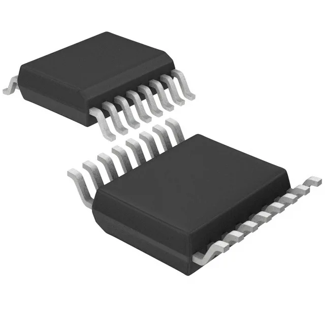
It is supplied in a 16-SOIC package on tape and reel, suitable for automated assembly. The 16-SOIC wide-body (7.50 mm width) footprint is common and well-supported for layout.