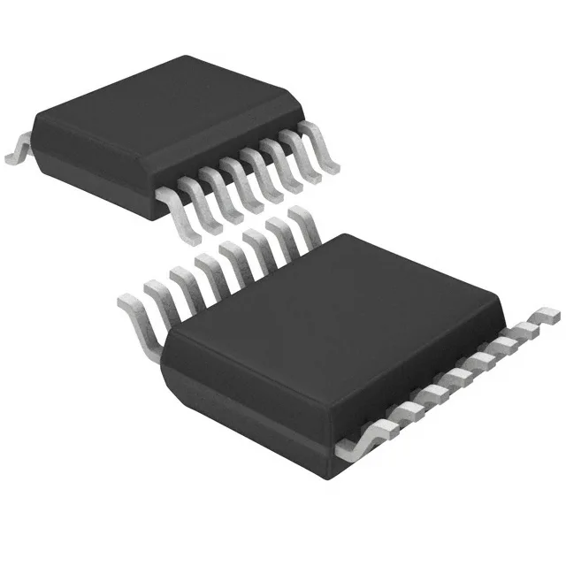
Half-bridge driver with 2 A peak gate drive and 500 V bootstrap
The IR2110STRPBF is a half-bridge gate driver from Infineon that sources and sinks 2 A peak current to the gate of an IGBT or N-Channel MOSFET. The 2 A peak output means the driver can charge a typical 10 nC gate capacitance in about 5 ns, keeping switching losses low in a 100 kHz converter. The bootstrap supply supports a high-side voltage up to 500 V, which sets the maximum DC bus voltage for the half-bridge leg.
Supply range and logic thresholds for mixed-voltage systems
The driver operates from a 3.3 V to 20 V supply, so it can run directly from a 3.3 V microcontroller rail or a 15 V bias supply without an intermediate regulator. The logic input thresholds are 6 V for VIL and 9.5 V for VIH, which means a 3.3 V logic signal will not reliably trigger the driver — the logic supply must be at least 5 V, or a level shifter is needed between the MCU and the driver input.
Switching speed and dead-time budget
Typical rise time is 25 ns and fall time is 17 ns into a standard load. These fast edges reduce the dead-time needed between high-side and low-side conduction, which improves efficiency at high switching frequencies. The independent channel architecture means each output is controlled separately, so the dead-time is set by the external PWM timing, not by internal cross-conduction delays.
Temperature rating and package for motor-drive environments
The 16-SOIC package with 7.50 mm body width is a common footprint for power drivers; the 0.295-inch width requires a 4-layer PCB for adequate thermal dissipation through the copper pours.
Active production status and sourcing posture
Infineon lists no end-of-life notice for this base product number.