Conduction and switching parametrics for the BOM engineer
The IPA60R380P6: Maximum on-resistance is 380 mOhm at 3.8 A drain current with a 10 V gate drive — this is the conduction loss anchor at the rated operating point. At 10.6 A the Rds(on) will be higher due to current-dependent effects, so budget the full-load conduction loss from the typical output characteristic curve, not the 3.8 A spec point. Gate charge totals 19 nC at 10 V Vgs — a modest figure that keeps the gate-drive energy per switching cycle low. Input capacitance Ciss is 877 pF at 100 V Vds — this sets the switching loss component from the gate-driver's ability to charge/discharge the Miller plateau region. The low Ciss relative to the 600 V rating means the device is optimised for fast switching rather than soft-switching resonant topologies. Maximum power dissipation is 31 W at case temperature — the TO-220 Full Pack's isolated tab means the thermal path goes through the plastic body to a heatsink, not a direct metal tab. Expect higher thermal resistance than a standard TO-220; the 31 W ceiling is the absolute limit, not a continuous operating point.
Package and mounting — isolated tab changes the thermal plan
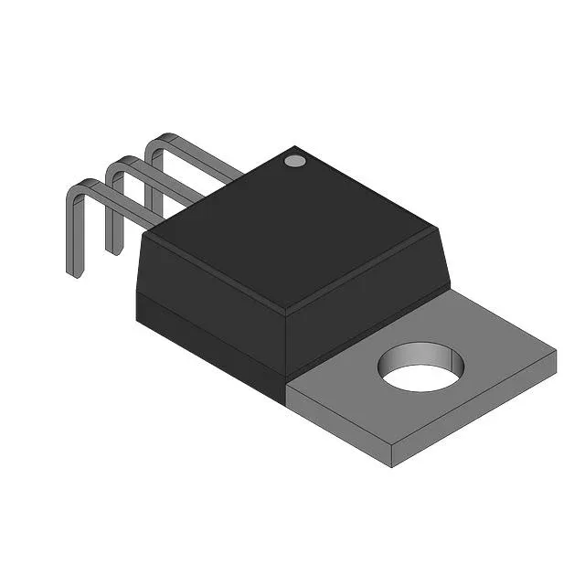
The TO-220-3 Full Pack (PG-TO220-3-111) has a fully isolated plastic body — the mounting hole and back surface are non-conductive, so no insulating pad or washer is needed between the device and a grounded heatsink. This simplifies assembly but raises the junction-to-case thermal resistance compared to a standard TO-220 with a metal tab. Operating junction temperature range is -55 °C to 150 °C — the full industrial temperature band. The 150 °C absolute maximum junction temperature is the hard ceiling; derate the continuous drain current above 100 °C case temperature per the datasheet curve.
Gate drive and threshold margins
Gate-source voltage maximum is ±20 V — the gate oxide can tolerate standard 12 V or 15 V gate drives with margin. The recommended drive voltage for achieving the rated Rds(on) is 10 V, as stated in the spec.