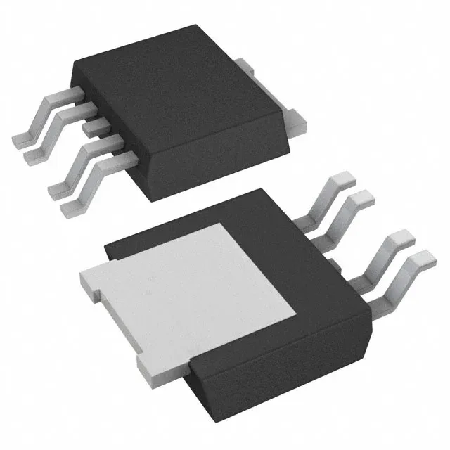
Package and board integration — PG-TO252-5-11
The BTF3050TEBATMA1 ships in a PG-TO252-5-11 package, a 4-lead plus tab DPak variant with a surface-mount footprint. The 150°C TJ ceiling means the part can sit at 125°C ambient with a 25°C margin for self-heating at the rated 3A output.
40 mOhm Rds(on) — conduction loss floor at 3A
Typical on-resistance is 40 mOhm, specified at the N-channel low-side output. At 3A continuous output, the conduction loss is I²R = 0.36 W — this is the dominant thermal contributor at full load. The 40 mOhm figure is a typical value; the datasheet max at 150°C junction will be higher due to the positive temperature coefficient of the silicon, so the actual loss budget should use the max Rds(on) at the operating TJ. The load voltage range spans 3V to 28V, covering 12V and 24V automotive nominal rails plus the cold-crank and load-dump transients within the abs-max limits.
Fault protection set — current limit, thermal, overvoltage, reverse current, short circuit
The BTF3050TEBATMA1 integrates five protection domains: fixed current limiting, over-temperature shutdown, over-voltage clamp, reverse current blocking, and short-circuit protection. The fixed current limit engages before the output current exceeds the 3A continuous rating — the limit threshold is set internally, so no external sense resistor is needed. Over-temperature shutdown protects against sustained fault conditions; the part auto-restarts when the junction cools, which means the downstream load sees a pulsed current during a hard short. The slew-rate controlled output (non-inverting input, 1:1 ratio) limits the turn-on and turn-off edge rates, reducing EMI radiated from the load wiring. This is relevant for unshielded harness runs in the engine bay where conducted emissions must stay below CISPR 25 Class 5 limits.