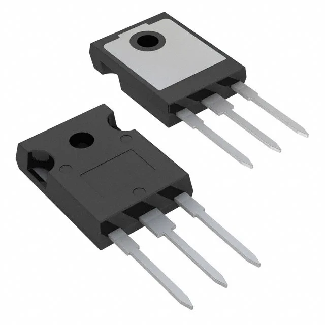
Infineon Technologies AIKW50N65DF5XKSA1 — Logic ICs

Infineon AIKW50N65DF5XKSA1 Trenchstop 5 IGBT, 650 V, 50 A

MPNAIKW50N65DF5XKSA1
End of Life

Infineon Trenchstop™ 5, AIKW50N65DF5XKSA1, 650 V, 50 A IGBT, Trench, Standard input, 1018 nC gate charge, 270 W, TO-247-3, AEC-Q101, -40°C to 175°C.

$9.16Ref. price · indicative, final on quote
PackagingTO-247-3
StockContact for availability
MOQ1 pcs
  • 100% new & originalTraceable channels only — no refurbs, no pulls, no remarked parts.
  • Date & lot codes on quoteStated per line before you commit; label photos on request.
  • MSL-compliant ESD packingMoisture-sealed bags with indicator cards; reels photo-verified.
  • PayPal buyer protectionPay by T/T, PayPal or Payoneer — card payments covered end to end.

Specifications

AIKW50N65DF5XKSA1 Technical Specifications
ParameterValue
SeriesTrenchstop™ 5
IGBT typeTrench
Input typeStandard
Mounting typeThrough Hole
Voltage - collector emitter breakdown650 V
Current - collector pulsed150 A
Power - max270 W
Operating temperature-40°C ~ 175°C (TJ)
GradeAutomotive
PackageTube
Gate charge1018 nC
QualificationAEC-Q101
CaseTO-247-3
Test condition400V, 25A, 12Ohm, 15V
Switching energy490µJ (on), 140µJ (off)
Td (on/off) @ 25°C21ns/156ns
Vce(on) (Max) @ vge, ic2.1V @ 15V, 50A

Product details

What the 650 V / 50 A rating buys you in a traction inverter

The Infineon AIKW50N65DF5XKSA1 is a 650 V, 50 A Trenchstop™ 5 IGBT in a TO-247-3 through-hole package, qualified to AEC-Q101 and rated for a 175°C junction temperature. It targets hard-switched traction inverters, on-board chargers, and DC-DC converters in hybrid and electric vehicles where the DC-link sits at 400 V nominal. The 650 V breakdown gives about 250 V of headroom above a 400 V bus — enough for typical load-dump and switching overshoot without derating into the next voltage class.

Switching loss budget at 20–50 kHz

Under the test condition of 400 V, 25 A, 12 Ω gate resistance, and 15 V gate drive, the part switches 490 µJ during turn-on and 140 µJ during turn-off. That asymmetry — roughly 3.5:1 — is typical for a Trench IGBT optimised for low Vce(on), and it means the turn-on loss dominates the total. A designer budgeting for a 20 kHz PWM rate should plan for roughly 12.6 W of switching loss per device at that operating point, before factoring in the gate-driver's 1018 nC charge requirement. The 21 ns turn-on delay and 156 ns turn-off delay are tight enough for dead-time compensation in a typical motor-control loop.

Automotive-grade qualification — what AEC-Q101 means on the shop floor

This part carries an Automotive grade label and AEC-Q101 qualification. The ROHS3 compliance is confirmed in the lifecycle record. Lifecycle status is Active, so no NRND or last-time-buy horizon is on the table for production planning.

Package and thermal path

The PG-TO247-3-41 package is a standard TO-247-3 outline with a fully isolated tab. The 270 W power dissipation rating assumes the case is held at 25°C — in a real 85°C coolant loop, derate that to roughly 170 W using the junction-to-case thermal resistance typical of the package. Through-hole mounting suits a bolted heatsink interface; the large copper tab carries the bulk of the dissipation.

Frequently asked questions

Will AIKW50N65DF5XKSA1 drop into a panel specified around IHW30N120R5XKSA1?

No. The IHW30N120R5XKSA1 is a 1200 V / 30 A device with a different gate charge (235 nC) and switching energy profile. Although both are TO-247-3, the AIKW50N65DF5XKSA1 is a 650 V / 50 A part optimised for a lower-voltage, higher-current application. The drive and loss calculations differ significantly; a board designed for the 1200 V part would need re-verification of the gate-driver and snubber.

What compliance documentation does Infineon provide for this part?

The part is ROHS3 compliant. For PPAP, AEC-Q101 qualification data, and REACH declarations, these are typically available from Infineon upon request through your sourcing channel.