What the 0.5pF capacitance buys you on an HDMI line
At 1 MHz the D5V0F4U10MR-13 presents just 0.5 pF of line loading per channel. That is low enough to keep the differential impedance of an HDMI trace within the 100-Ohm ±15% window without adding a compensation stub or a series resistor to kill the edge rate. Four unidirectional channels in a single 10-MSOP package means one part covers the four TMDS data pairs on an HDMI source or sink port. The steering (rail-to-rail) topology shunts ESD strikes to the supply rails rather than letting the spike punch through the silicon of the HDMI transmitter or receiver. Clamping at 12 V with a 3 A 8/20 µs pulse means a 15 kV air-discharge ESD event — which peaks well above 30 A — gets folded down to a voltage the HDMI PHY's own internal diodes can survive. The 5.5 V max reverse standoff sits above the 3.3 V HDMI supply rail so the device does not clip the signal during normal operation.
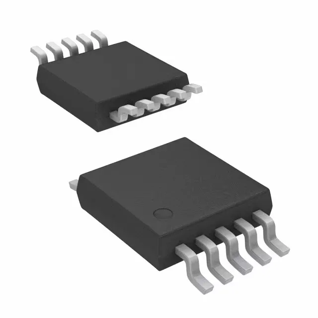
10-TFSOP / 10-MSOP footprint, 3.00 mm body width. The 0.50 mm lead pitch demands a soldermask-defined pad with a 0.25 mm stencil aperture for consistent solder paste volume. The exposed die attach pad on the bottom of the MSOP package is the primary thermal path — a via cluster under the pad drops the junction-to-board thermal resistance below 60 °C/W. Surface-mount assembly on a standard FR-4 board with a 260 °C peak reflow profile. The -65 °C to +150 °C junction temperature range covers both the soldering thermal shock and the full automotive ambient envelope, though the device is not formally AEC-Q101 qualified.
Sourcing and compliance posture
The base product number D5V0F4 anchors a family of steering TVS arrays in the same package.