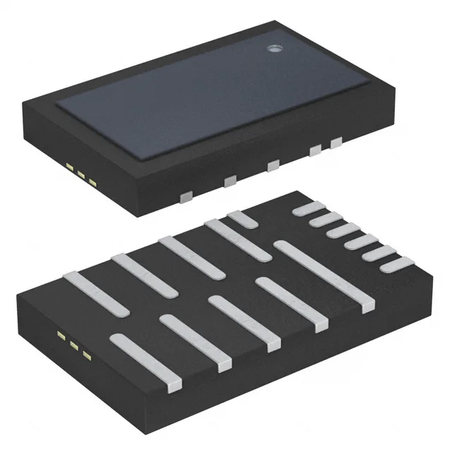
The VT1697SBFQ: The 0.50 mm pitch on the outer leads demands a solder-mask-defined pad with a 0.25 mm stencil aperture for consistent fillet formation. Supplied in a Tray, not tape-and-reel — this matters for pick-and-place setup: the tray orientation must match the feeder's pocket map, and the tray count per reel feeder is limited. For high-volume reels, request the alternate packaging variant if available.
What the peak current rating means for your load
The 55 A peak output is the maximum current the half-bridge can deliver in a single pulse — it is not the continuous rating. For an inductive load like a solenoid or motor winding, the peak current occurs during the turn-on transient and decays according to the load time constant and the PWM duty cycle. The actual RMS current the device sees is duty-cycle-limited; a 55 A peak at 10 % duty gives an RMS of about 17.4 A, which is within the package's thermal capability with adequate board copper. The current limiting fault protection clamps the output before the die exceeds its SOA, but the thermal limit is the binding constraint for sustained operation. The load voltage range is 8.5 V to 14 V — this covers a 12 V nominal rail with margin for battery float charging (14 V) and deep discharge (8.5 V). The logic supply is separate: 1.71 V to 1.98 V, which is a 1.8 V nominal rail.
Diode emulation and status flag — what they do on the bench
Diode emulation means the low-side FET turns off when the inductor current reverses direction during the dead-time — this prevents negative current from flowing back into the supply rail. The Status Flag output goes low when any fault condition (current limit, over-temp, short circuit, UVLO) is active — it is an open-drain signal that can be pulled up to the logic supply voltage and read by a GPIO on the controller. The flag latches until the fault clears and the PWM input is toggled low for a reset period.