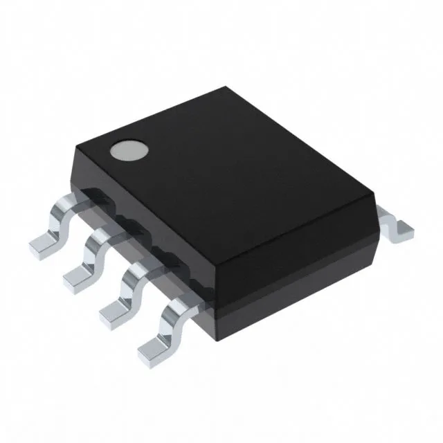
Buck-boost controller for negative rail generation
The Maxim Integrated MAX775ESA+ is a single-output buck-boost PWM controller designed to generate a negative regulated voltage from a positive input rail. It operates in a step-up/step-down topology, meaning the output can be above, below, or inverted relative to the input — here it's configured for a negative output. The controller drives an external transistor switch (no internal FET), giving the designer flexibility to size the power stage for the load current. Switching frequency is fixed at 300 kHz, a balance between inductor size and switching losses that keeps the magnetics under 10 µH for most designs. Supply range spans 3V to 16.5V, covering standard 3.3V, 5V, and 12V rails.
Most buck-boost controllers produce a positive regulated output. The output configuration is listed as Negative, so the feedback network and compensation will be referenced to the negative rail.
300 kHz switching — inductor and filter design
The fixed 300 kHz switching frequency is on the lower side by modern standards — many controllers now run at 500 kHz to 2 MHz. The trade-off is lower switching losses and better efficiency at higher input voltages, but larger inductors and output capacitors. Plan for a 10 µH to 47 µH inductor depending on the output current and input voltage. The 300 kHz fundamental also simplifies conducted EMI filter design if you're targeting CISPR 25 or FCC Class B, since the harmonics are more widely spaced than a 2 MHz switcher.