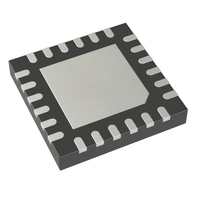
Analog Devices MAX7358ETG+ — Logic ICs

MAX7358ETG+ I2C 8:1 Multiplexer, 24-Ohm On-Resistance

MPNMAX7358ETG+
End of Life

Analog Devices MAX7358ETG+, I²C 8:1 multiplexer, 24-Ohm max on-resistance, 2.3V to 5.5V single supply, -40°C to 85°C, 24-TQFN (4x4) surface mount.

$4.79Ref. price · indicative, final on quote
Packaging24-WFQFN Exposed Pad
RoHSROHS3 Compliant
Sourced new & surplus through independent channelsAuthenticity-screened · ESD-safe packingListing updated Aug 2026

Specifications

MAX7358ETG+ specifications
ParameterValue
MountingSurface Mount
Voltage - supply, single (V+)2.3V ~ 5.5V
Operating temperature-40°C ~ 85°C (TA)
PackageTube
FeaturesBi-Directional
ApplicationsI²C
Case24-WFQFN Exposed Pad
Channels1
On-State resistance24Ohm
Multiplexer (Demultiplexer circuit)8:1

Product details

8:1 I²C bus multiplexer in a 4x4 mm TQFN

The 24-Ohm max on-state resistance keeps the bus rise time within spec even with a few hundred picofarads of trace and connector capacitance on each channel. It runs from a single 2.3V to 5.5V supply, so it fits both 3.3V and 5V I²C domains without a level translator. The 8:1 mux/demux circuit is bi-directional — data and clock pass through the selected channel in both directions, which is the standard I²C mux topology for isolating bus segments or resolving address conflicts.

Industrial temperature range and active production

ROHS3 compliant for EU and similar restricted-material regulations.

Housed in a 24-WFQFN with exposed pad, the 4x4 mm body fits tight PCB layouts. Surface-mount only; ships in Tube.

Frequently asked questions

Is MAX7358ETG+ RoHS compliant?

Yes, it is ROHS3 compliant.

What is the difference between MAX7358ETG+ and PCA9548A?

Both are 8:1 I²C multiplexers in similar packages. The MAX7358ETG+ specifies a 24-Ohm max on-resistance versus the PCA9548A's typical 15-Ohm (not a direct max-to-max comparison), and the MAX7358ETG+ runs from 2.3V to 5.5V while the PCA9548A is rated 2.3V to 5.5V as well — the real difference is in the address pin mapping and the reset behavior; check the respective datasheets for the specific logic thresholds and power-up defaults.