8-channel low-side driver with SPI control
The MAX4822ETP+T is an 8-channel low-side N-Channel power driver from Analog Devices, designed to switch relay coils, solenoids, and other inductive loads in a 1:8 input-to-output ratio. Each output is rated for 70mA continuous with a typical on-resistance of 2.7Ω, and the load supply range spans 2.3V to 5.5V — covering common 3.3V and 5V relay and solenoid rails. Control is handled over an SPI interface, allowing a microcontroller to latch all eight outputs with a single chip-select transaction rather than toggling individual GPIO lines.
The 2.7Ω typical on-resistance at 70mA produces a voltage drop of roughly 190mV across the driver — well under 0.2V, so the relay coil sees nearly the full supply voltage. A higher Rds(on) would rob the coil of holding current and risk dropout on marginal supplies. With a 2.3V minimum load supply, the driver can switch a 3V-rated relay from a 2.5V rail and still stay within the output voltage compliance. The low-side configuration means the load connects between V_load and the driver drain — the driver sinks to ground when turned on. The non-inverting input logic means a logic-high on the SPI data bit turns the corresponding output on. There is no built-in charge pump or boost — the gate drive comes from the internal charge pump that runs from the SPI bus voltage, so the driver does not require a separate Vcc supply (Vcc/Vdd not required).
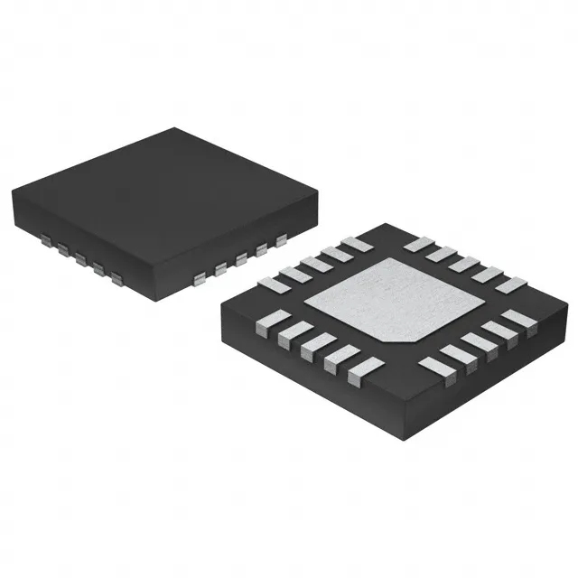
20-TQFN package and board integration
The 0.5mm pitch QFN footprint requires careful solder-paste stencil design to avoid bridging between adjacent pins.