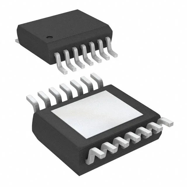
Analog Devices MAX20051AUD/V+T — DC-DC Power Modules

MAX20051AUD/V+T LED Driver IC, 2A Buck Regulator, 14-TSSOP

MPNMAX20051AUD/V+T
End of Life

Maxim Integrated MAX20051AUD/V+T, DC DC Regulator LED Driver, Step-Down (Buck) topology, 2A output, 4.5V to 65V input, 400kHz switching, Analog and PWM dimming, 14-TSSOP-EP exposed pad, -40°C to 125°C.

$4.74Ref. price · indicative, final on quote
Packaging14-TSSOP (0.173", 4.40mm Width) Exposed Pad
RoHSROHS3 Compliant
Sourced new & surplus through independent channelsAuthenticity-screened · ESD-safe packingListing updated Aug 2026

Specifications

MAX20051AUD/V+T specifications
ParameterValue
TypeDC DC Regulator
MountingSurface Mount
Voltage - output4.875V ~ 5.125V
Voltage4.5V
Current - output (Channel)2A
Frequency400kHz
I/O channels1
Operating temperature-40°C ~ 125°C
DimmingAnalog, PWM
PackageTape & Reel (TR); Cut Tape (CT)
TopologyStep-Down (Buck)
ApplicationsCommercial & Industrial Lighting
Case14-TSSOP (0.173\", 4.40mm Width) Exposed Pad
Internal switchYes

Product details

2A buck LED driver with wide input range

The Maxim Integrated MAX20051AUD/V+T is a DC-DC regulator LED driver built around a step-down (buck) topology, delivering up to 2A per channel from a 4.5V to 65V supply rail. It integrates the switching FET internally, so the external BOM stays compact — just the inductor, sense resistor, and a few passives. The 400kHz fixed switching frequency keeps the magnetics small while staying clear of AM band noise in automotive and industrial lighting panels.

Analog and PWM dimming — two control paths

Dimming is supported through both analog and PWM methods, giving the board designer flexibility. Analog dimming adjusts the LED current linearly via a control voltage, useful for smooth brightness ramps in architectural lighting. PWM dimming switches the output at a duty cycle, preserving color temperature in RGB or tunable-white fixtures.

Housed in a 14-TSSOP package with an exposed pad (14-TSSOP-EP), the part relies on the paddle for heat sinking. Without that thermal path, the 2A output will push the junction above the 125°C limit in continuous operation.

No successor or second-source alternate is recorded in the official cross-reference, so the BOM should be qualified with this exact ordering code. For dual-sourcing or supply resilience, a parametric search against the same 2A, 65V, buck-LED-driver spec is the practical route.

Frequently asked questions

What is the closest pin-compatible alternative to MAX20051AUD/V+T?

No official pin-compatible second source is recorded in the cross-reference data. The MAX20051 family shares the same 14-TSSOP-EP footprint and pinout across current options, so a sibling within that family (e.g., a different current tier) would be the closest parametric match, but the exact ordering code MAX20051AUD/V+T should be qualified as the primary BOM line item.

How to use MAX20051AUD/V+T in a buck LED driver?

The part is a self-contained buck regulator with an integrated switch. The typical application connects the LED string between the output and ground, with an inductor and sense resistor setting the current. The 400kHz switching frequency allows a small inductor (typically 22 µH to 47 µH range). Analog dimming is applied to the control pin; PWM dimming drives the enable pin with a logic-level signal. The exposed pad must be soldered to a thermal plane for heat dissipation at 2A.