Analog Devices MAX15301AA02+CJK — Analog & Data Acquisition

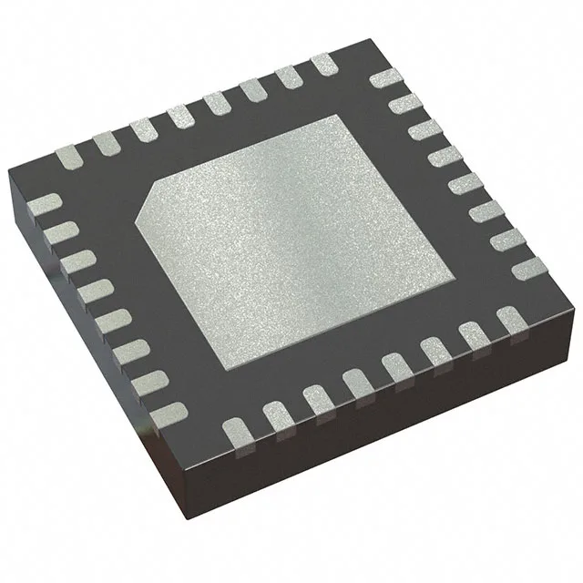
MAX15301AA02+CJK Buck Controller, PMBus, 4.5V-14V, 32-TQFN

MPNMAX15301AA02+CJK
End of Life

Maxim MAX15301AA02+CJK, Step-Down (Buck) Controller, PMBus, 1 Output, Transistor Driver, 4.5V to 14V Supply, 300kHz to 1MHz, 32-TQFN (5x5mm), -40°C to 85°C.

$9.83Ref. price · indicative, final on quote
Packaging32-WFQFN Exposed Pad
RoHSROHS3 Compliant
Sourced new & surplus through independent channelsAuthenticity-screened · ESD-safe packingListing updated Aug 2026

Specifications

MAX15301AA02+CJK specifications
ParameterValue
Output typeTransistor Driver
MountingSurface Mount
Voltage - supply (Vcc (Vdd))4.5V ~ 14V
Frequency300kHz ~ 1MHz
I/O channels1
Output phases1
Duty cycle95%
InterfacePMBus
Operating temperature-40°C ~ 85°C (TA)
PackageTube
FunctionStep-Down
TopologyBuck
Clock syncYes
Case32-WFQFN Exposed Pad
Control featuresCurrent Limit, Enable, Power Good
Output configurationPositive
Synchronous rectifierYes

Product details

Switching frequency is programmable from 300kHz to 1MHz, with clock sync available. A lower frequency (300-500kHz) reduces switching losses and suits higher step-down ratios; 1MHz lets you shrink the output inductor and capacitor, saving board area at the cost of slightly higher FET gate-drive loss. Control features include current limit, enable, and power-good output. The power-good flag is open-drain and asserts when the output is within regulation — useful for sequencing or fault reporting to a CPLD or supervisor. The enable pin lets the system hold the controller off until the input rail is stable. The package is surface-mount, compatible with standard reflow profiles.

It is not qualified to AEC-Q100, so it is not aimed at automotive under-hood or chassis domains. The 95% maximum duty cycle allows operation close to dropout — useful when the input rail sags under load.

For a production BOM line that needs PMBus telemetry on a 12V buck rail, this part is a current-design fit with no LTB risk.

Frequently asked questions

How do I program MAX15301AA02+CJK via PMBus?

Programming is done over the PMBus (I²C-based) serial interface. The controller responds to standard PMBus commands for output voltage trim, fault limits, and telemetry readback. A typical sequence: power up the Vcc rail, hold the enable pin low until the bus is stable, then send the desired VOUT_COMMAND and OPERATION commands. No on-chip nonvolatile memory is mentioned — the configuration is set at each power-up via the bus.