Isolation barrier and timing budget
The MAX14936EAWE+ provides 5000 Vrms galvanic isolation via capacitive coupling — this is reinforced-grade isolation for safety isolation in mains-connected equipment and for breaking ground loops in noisy industrial signal chains. The 25 kV/µs typical common-mode transient immunity (CMTI) means the output stays valid when a 1500 V/µs motor-drive switching edge slams the barrier; a lower CMTI part would glitch the logic state. Propagation delay max is 27.5 ns (tpLH) and 28.8 ns (tpHL), with a pulse-width distortion ceiling of 2.6 ns. For a 25 Mbps NRZ signal (40 ns bit period), the delay consumes about 70% of the bit time — the receiving FPGA or ASIC must tolerate that skew. The 2 ns typical rise/fall edges keep the signal clean into a standard CMOS input without excessive ringing.
Supply rails and channel configuration
There is no integrated DC-DC converter for isolated power (no isolated power output), so the secondary side needs its own supply rail. Four unidirectional channels are arranged as two inputs on side 1 and two on side 2. This 2/2 split suits bidirectional data paths (SPI with MISO/MOSI plus a clock and chip-select) where each direction needs two lines. If you need more than four channels or bidirectional I/O on the same channel, look at the MAX1493x family with configurable direction.
Package, temperature grade, and production status
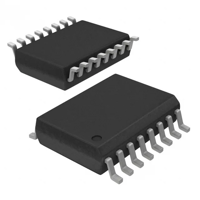
Housed in a 16-pin SOIC wide-body (7.50 mm body width) — the 0.295-inch lead span gives >8 mm creepage distance for 5000 Vrms reinforced isolation per IEC 60950-1. Surface-mount assembly requires a standard reflow profile for the lead-free finish (ROHS3 compliant).