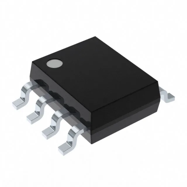
What the 150 Mbps data rate and 9.2 ns propagation delay mean for your timing budget
The MAX12930FASA+T is a 2-channel unidirectional digital isolator from Analog Devices, built with capacitive coupling technology. This combination sets the throughput ceiling for the isolation channel: at 150 Mbps, the bit period is roughly 6.67 ns, so the propagation delay consumes about 1.4 bit periods — the receiver still has enough timing margin for a clean eye diagram, but the PCB trace length between the isolator output and the downstream load must be kept short to avoid adding skew. The 2 ns maximum pulse-width distortion is the critical spec for duty-cycle-sensitive protocols like PWM motor-control signals or SPI clock lines. If the high-time and low-time at the output differ by more than 2 ns from the input, the downstream controller may misinterpret the pulse width. For a 50% duty-cycle 10 MHz clock, a 2 ns distortion represents a 2% duty-cycle error — acceptable for most logic, but tight for precision ADC conversion triggers.
3750 Vrms isolation and 50 kV/µs CMTI — the safety and noise-rejection envelope
The 3750 Vrms isolation voltage qualifies this part for reinforced insulation in medical equipment (per IEC 60601-1) and industrial motor drives (per IEC 61800-5-1). The 50 kV/µs typical common-mode transient immunity means the isolator maintains data integrity when the ground plane between the two sides jumps by thousands of volts per microsecond — exactly the condition in a motor-drive inverter leg when the IGBT switches off and the DC-bus voltage rings across the parasitic capacitance. The 1.6 ns typical rise time and 1.4 ns typical fall time are fast enough that the signal edge contains significant energy above 200 MHz. The PCB layout must treat the isolator output trace as a transmission line if the load is more than about 30 mm away — a series termination resistor at the source matches the line impedance and prevents the reflected edge from corrupting the next bit.
Both sides share the same supply pin — there is no separate VddA and VddB — so this part bridges between two domains at the same nominal voltage. If the application requires a 3.3 V-to-5 V level shift, a different variant in the MAX12930 family with split supplies would be needed. Because the part has 2 channels, both on side 1 (inputs side 1/side 2: 2/0), the data flows only from side 1 to side 2. There is no reverse-direction channel. If the design needs bidirectional isolation (e.g., for an SPI bus with MISO and MOSI), two of these parts or a different order code with mixed-direction channels would be required.
The surface-mount assembly process is well-characterised: the 1.27 mm pin pitch allows hand-soldering with a fine-tip iron, and the package body is compatible with no-clean flux residues. A CT option is available for prototype or low-volume builds.
Active lifecycle and compliance — no end-of-life risk for current designs
The part is ROHS3 compliant, meaning no RoHS exemptions are claimed — suitable for EU and global markets without restriction. The technology is capacitive coupling, which offers lower power per channel than optocouplers and better immunity to magnetic fields than inductive coupling. The General Purpose type means it is not optimised for a specific protocol like I²C or RS-485 — it is a raw digital isolator that passes any logic-level signal up to 150 Mbps.