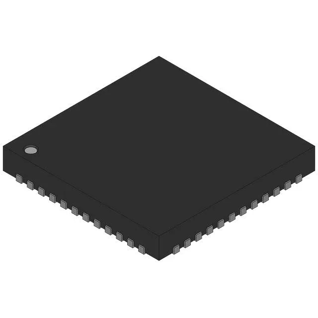
The LTC2232IUK#TRPBF is a 10-bit pipelined ADC from Analog Devices, sampling at 105 MSPS. That rate digitizes input signals up to roughly 50 MHz (Nyquist-limited) — enough for intermediate-frequency (IF) sampling in communications receivers, radar digitizers, or high-speed data acquisition. The 10-bit resolution gives a theoretical SNR of about 62 dB, which sets the noise floor for the system; if your front-end amplifier noise is below that, the ADC becomes the limiting factor.
Input flexibility and supply simplicity
The ADC accepts both differential and single-ended inputs, selected by the input configuration. Differential mode gives better common-mode rejection — important when the signal source is a transformer-coupled IF stage or a balanced sensor. The reference can be driven externally or generated internally, so you can match the ADC's full-scale range to the signal amplitude without an external reference IC. Both the analog and digital supplies run from a single 3.1 V to 3.5 V rail — no separate 1.8 V core supply needed. That simplifies the power tree: one LDO or buck converter feeding both AVDD and DVDD, with decoupling at each pin. The parallel data interface outputs 10 bits at 105 MHz, so the PCB layout needs controlled impedance on the data lines if the trace length exceeds about 50 mm.
Package and reflow — what the QFN needs from you
The 48-QFN (7x7 mm) with exposed pad requires a thermal land on the PCB — the datasheet's recommended footprint includes a central pad connected to ground with at least nine thermal vias. The exposed paddle is the primary heat path; without it the junction temperature rises above the 85°C ambient limit at full sampling rate. The package is MSL-rated per JEDEC; bake it before reflow if the floor life has been exceeded, or moisture trapped under the paddle causes popcorning in the oven. The 0.5 mm pitch QFN pads are solder-mask defined — the stencil aperture should be slightly smaller than the pad to avoid bridging. A 0.125 mm stencil thickness works for most reflow profiles; the exposed paddle gets a larger aperture (typically 50-70% coverage) to control solder volume and prevent the part from floating off the pad.