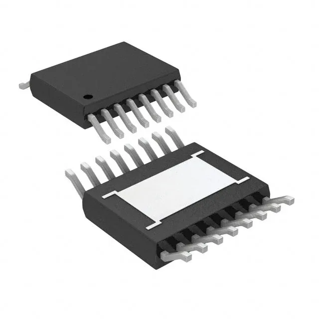
3 A from a 42 V rail — the thermal pad tells the story
The LT8609AIMSE16#PBF is a 3 A continuous-rated synchronous buck regulator from Analog Devices, stepping down from a 3 V to 42 V input rail down to an adjustable output as low as 0.782 V. That 42 V ceiling covers 24 V industrial supplies with margin for transients, and the 3 A output handles modest point-of-load rails for FPGAs, sensors, or communication modules without needing an external catch diode — the synchronous rectifier is on-die. The package is a 16-lead TFSOP with an exposed pad (MSOP-EP footprint). That pad is the primary thermal path — the datasheet's junction-to-ambient figure assumes a solid copper pour and via stitching under the pad. On a repair bench, a scorched LT8609 often traces back to a board layout where the thermal vias were omitted or the copper plane was split under the part.
Switching frequency — synchronize or spread the noise
The switching frequency is programmable from 200 kHz to 2.2 MHz via a resistor, or it can be synchronized to an external clock in that same range. Running at 2.2 MHz shrinks the inductor to a 0603 footprint but pushes the switching harmonics above the AM band — useful if the regulator shares a board with a radio receiver. Dropping to 200 kHz cuts switching losses by about a factor of ten, which matters when the input voltage is high and the duty cycle is low. At 125°C junction the internal FET Rds(on) roughly doubles from the 25°C value, so the 3 A output derates; the datasheet's thermal model should be run with the actual ambient and copper area before committing the layout.