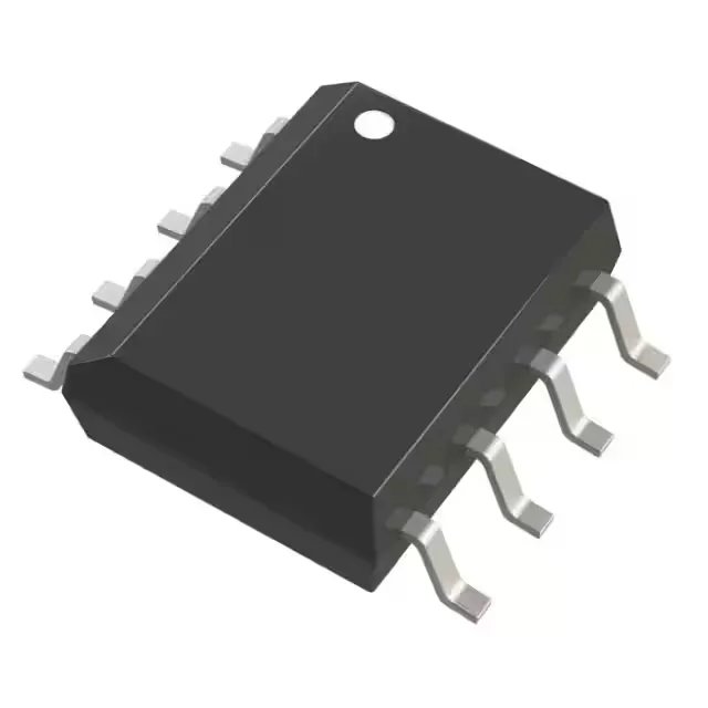
What the 1.5A switch current buys you in a buck-boost converter
The LT1107IS8#PBF integrates a 1.5A switch rated for up to 50V, which sets the output power ceiling for a given topology — in a boost configuration from a 5V input, that switch current supports roughly 5W output before hitting the current limit, while in a buck configuration the same switch can deliver 1.5A to the load directly. Switching at 63 kHz means the inductor value lands in the 47-220 µH range for most designs — larger than a 500 kHz part would need, but the switching losses stay low enough that the SOIC-8 package can dissipate the heat without a heatsink in still air up to 85°C ambient.
Input and output voltage range — where this regulator fits
The 2V minimum input lets it start from a near-depleted Li-ion cell or a single alkaline battery, while the 30V maximum input covers 24V industrial rails with margin for transients — the output can be set anywhere from 1.25V up to 50V (limited by the switch breakdown), so a single design can generate a 3.3V logic rail, a 12V bias supply, or a 48V phantom power feed from the same PCB layout. The output configuration accepts positive or negative regulation — the same pinout can generate a -5V rail from a +5V input using the inverting topology, which saves a dedicated negative regulator on the board.
Active lifecycle and compliance — no obsolescence risk
ROHS3 compliant and supplied in a standard tube — the 8-SOIC package is a JEDEC-compatible footprint shared by hundreds of regulators, so the PCB land pattern is well-characterised and the reflow profile is standard lead-free.