Analog Devices ADUM4151BRIZ-RL — Digital Isolators

ADUM4151BRIZ-RL SPI Digital Isolator, 34 Mbps, 5000 Vrms

MPNADUM4151BRIZ-RL
End of Life

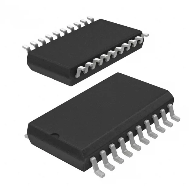
Analog Devices ADUM4151BRIZ-RL, iCoupler®, SPIsolator™ series, SPI digital isolator, 7 unidirectional channels (5/2), 34 Mbps data rate, 5000 Vrms isolation, 25 kV/µs CMTI, 3 V to 5.5 V supply, -40°C to 125°C, 20-SOIC-IC, surface mount, tape & reel.

$11.96Ref. price · indicative, final on quote
Packaging20-SOIC (0.295", 7.50mm Width)
StockContact for availability
MOQ1 pcs
  • 100% new & originalTraceable channels only — no refurbs, no pulls, no remarked parts.
  • Date & lot codes on quoteStated per line before you commit; label photos on request.
  • MSL-compliant ESD packingMoisture-sealed bags with indicator cards; reels photo-verified.
  • PayPal buyer protectionPay by T/T, PayPal or Payoneer — card payments covered end to end.

Specifications

ADUM4151BRIZ-RL Technical Specifications
ParameterValue
TypeSPI
SeriesiCoupler®, SPIsolator™
Channel typeUnidirectional
Mounting typeSurface Mount
Voltage3V ~ 5.5V
Voltage - isolation5000Vrms
Isolated powerNo
Operating temperature-40°C ~ 125°C
Pulse width distortion2ns
PackageTape & Reel (TR); Cut Tape (CT)
Data rate34Mbps
TechnologyMagnetic Coupling
Case20-SOIC (0.295\", 7.50mm Width)
Number of channels7
Inputs - side 1/Side 25/2
Rise (Fall time)2.5ns, 2.5ns
Propagation delay tpLH (tpHL)14ns, 14ns
Common mode transient immunity25kV/µs

Product details

SPI isolator with the channel count that matches your bus

The ADUM4151BRIZ-RL is a 7-channel SPI digital isolator from Analog Devices in the iCoupler® and SPIsolator™ families. It uses magnetic coupling to provide 5000 Vrms of reinforced isolation across a 20-SOIC package. The channel configuration — 5 inputs on side 1, 2 on side 2 — is laid out for a full SPI bus plus two extra lines: clock, MOSI, MISO, chip-select, and a fifth side-1 signal (often a reset or busy line), with two side-2 inputs for interrupts or handshake signals. Data rate is 34 Mbps, enough for most SPI peripherals running at 20–30 MHz bus clocks without adding setup/hold margin problems. Propagation delay is 14 ns max, and pulse-width distortion stays under 2 ns, so the clock duty cycle doesn't degrade across the barrier.

At 34 Mbps, the ADUM4151BRIZ-RL can sustain a 17 MHz SPI clock with a full-cycle data window. The 14 ns propagation delay adds about half a clock period at 34 MHz, so you'll want to check the bus timing budget if your SPI master runs above 20 MHz. The 2.5 ns rise/fall time keeps the edges clean, and the 2 ns max pulse-width distortion means the clock duty cycle won't shift by more than 4% at 34 Mbps — no risk of violating hold times on the far side. For comparison, the ADUM4150ARIZ-RL runs at 40 Mbps but has only 6 channels (4/2 split), so the 4151 trades 6 Mbps of speed for the extra side-1 input.

5000 Vrms and 25 kV/µs CMTI — where this part lives

The 5000 Vrms isolation rating qualifies for reinforced insulation in medical (IEC 60601), industrial (IEC 61010), and grid-tie (IEC 62109) equipment. The 25 kV/µs common-mode transient immunity is the key spec for motor drives and inverters: when a 600 V IGBT switches in 50 ns, the dV/dt across the barrier can exceed 10 kV/µs, and a lower CMTI part would latch or corrupt data.

If you are dual-sourcing for supply resilience, the ADUM4150ARIZ-RL is a 6-channel (4/2) variant with 40 Mbps data rate — same package, same isolation rating, same temperature range — but the channel count and speed differ, so verify the pin function assignment before substituting.

Frequently asked questions

What is the closest functional second-source for ADUM4151BRIZ-RL?

It has 6 channels (4/2 split) and a 40 Mbps data rate, versus 7 channels (5/2 split) and 34 Mbps on the 4151. The channel count and pin mapping differ, so a board respin is needed for substitution.

Will ADUM4151BRIZ-RL drop into a panel originally built with ADUM4150ARIZ-RL?

No — the ADUM4151BRIZ-RL has 7 channels (5/2 split) while the ADUM4150ARIZ-RL has 6 channels (4/2 split). The pin assignments differ, so a direct drop-in without rewiring or a PCB change is not possible.