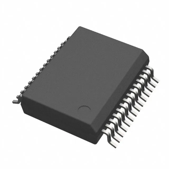
Automotive-qualified isolated gate driver for traction inverters and motor drives
The ADUM4138WBRNZ-RL is an Analog Devices isolated single-channel gate driver built around iCoupler magnetic coupling technology, rated Automotive grade with a -40°C to 150°C operating range. It delivers 6 A peak output current across a 12 V to 25 V output supply range, with 5000 Vrms galvanic isolation. Typical deployment includes traction inverters, on-board chargers, and high-voltage DC-DC converters where the AEC-Q100 qualification and reinforced isolation are mandatory for the PPAP package.
6 A peak drive — what it means for IGBT and MOSFET selection
The 6 A peak output current is the sourcing and sinking capability into the gate of a power switch. For a typical IGBT module with a gate charge of 1 µC, the ADUM4138WBRNZ-RL can switch it on in roughly 170 ns, assuming the 95 ns typical rise time. This matters for minimizing switching losses in hard-switched automotive inverters. The output supply range of 12 V to 25 V accommodates standard IGBT gate drive levels (typically 15 V) and allows headroom for desaturation protection circuits.
150 kV/µs CMTI — why it matters in switching power stages
Common-mode transient immunity of 150 kV/µs (minimum) means the gate driver maintains its output state when a fast high-voltage transient slams across the isolation barrier. In a half-bridge inverter leg switching 600 V at 50 kHz, the dv/dt at the switch node can exceed 50 kV/µs. A driver with lower CMTI would glitch, causing shoot-through. The 150 kV/µs rating gives margin for even the fastest SiC and GaN transitions.
Propagation delay and timing budget
Maximum propagation delays are 130 ns (low-to-high) and 121 ns (high-to-low), with rise and fall times of 95 ns and 100 ns typical. These numbers define the minimum dead-time you can program in the controller without risking cross-conduction.
It is ROHS3 compliant. For automotive OEM PPAP submissions, the AEC-Q100 qualification documentation is available from Analog Devices.