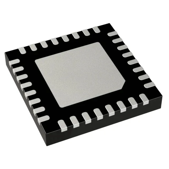
Analog Devices ADG2128YCPZ-REEL7 — Microcontrollers & Processors (MCU / MPU / DSP)

ADG2128YCPZ-REEL7 Analog Devices 12:8 Crosspoint Switch

MPNADG2128YCPZ-REEL7
End of Life

Analog Devices ADG2128YCPZ-REEL7 crosspoint switch, 12:8 multiplexer/demultiplexer, 210 MHz -3dB bandwidth, 50 Ohm on-state resistance, 32-LFCSP-VQ (5x5) exposed pad, I²C control, -40°C to +125°C.

$17.24Ref. price · indicative, final on quote
Packaging32-VFQFN Exposed Pad, CSP
StockContact for availability
Lead timeIn Stock wk
MOQ1 pcs
  • 100% new & originalTraceable channels only — no refurbs, no pulls, no remarked parts.
  • Date & lot codes on quoteStated per line before you commit; label photos on request.
  • MSL-compliant ESD packingMoisture-sealed bags with indicator cards; reels photo-verified.
  • PayPal buyer protectionPay by T/T, PayPal or Payoneer — card payments covered end to end.

Specifications

ADG2128YCPZ-REEL7 Technical Specifications
ParameterValue
Mounting typeSurface Mount
Voltage - supply, dual (V±)±5V
Voltage - supply, single (V+)12V
Operating temperature-40°C ~ 125°C (TA)
-3db bandwidth210MHz
PackageTape & Reel (TR); Cut Tape (CT)
FeaturesI²C
ApplicationsTelecommunications, Ultrasound
Case32-VFQFN Exposed Pad, CSP
Number of channels1
On-State resistance50Ohm
Multiplexer (Demultiplexer circuit)12:8

Product details

12:8 crosspoint switch with 210 MHz analog bandwidth

The ADG2128YCPZ-REEL7 is a 12:8 crosspoint switch array — any of 12 inputs can be routed to any of 8 outputs under I²C control, making it a full non-blocking matrix rather than a simple multiplexer. The 210 MHz -3 dB bandwidth means this part passes analog signals well into the VHF range — suitable for ultrasound transducer beamforming, telecom baseband routing, or video signal switching where signal integrity above 100 MHz matters.

On-resistance and signal path loss

Maximum on-state resistance is 50 Ohm — this sets the insertion loss through the switch. For a 50 Ohm system, the switch adds roughly 6 dB of attenuation in the signal path; for higher impedance loads the loss drops proportionally. The single 12 V supply or dual ±5 V rails give flexibility to match the analog signal swing. With ±5 V the switch handles bipolar signals up to the supply rails, useful for ultrasound echoes that swing below ground.

Package and rework considerations

The exposed pad needs a solder paste stencil opening that matches the datasheet footprint; under the hot-air station the part reflows evenly if the pad is properly tinned. Pin 1 is marked by a chamfer on the top-left corner of the package. The 0.5 mm pitch QFN lands are on the bottom; alignment under reflow is self-centering if the paste deposit is consistent across all 32 pads.

The wide range also suits automated test equipment where the switch sits near a heated device interface. Listed applications include telecommunications and ultrasound — both require the 210 MHz bandwidth and the non-blocking matrix topology to route multiple analog channels without crosstalk between paths.

ROHS3 compliant per the manufacturer's declaration — no restricted substances above the threshold limits for EU and global markets.

Frequently asked questions

What is the ADG2128YCPZ-REEL7's on-state resistance and why does it matter?

Maximum on-state resistance is 50 Ohm. This value determines the signal attenuation through the switch — in a 50 Ohm system the insertion loss is roughly 6 dB. For high-impedance loads the loss is lower, but the 50 Ohm spec sets the floor for signal path budgeting.

What supply voltages does the ADG2128YCPZ-REEL7 need?

It operates from a single 12 V supply or dual ±5 V rails. The dual supply option lets the switch pass bipolar analog signals that swing below ground, which is common in ultrasound and instrumentation front-ends.