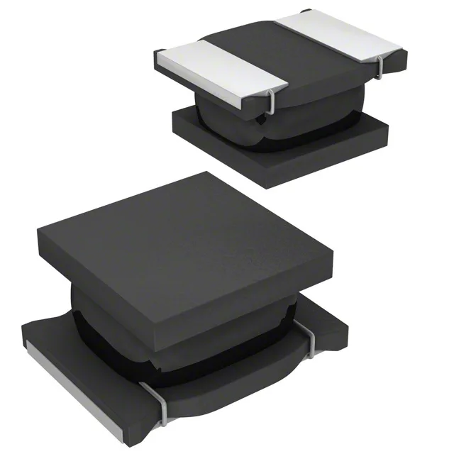
10 µH shielded power inductor for automotive DC-DC stages
The Murata LQH3NPZ100MMEL is a drum-core wirewound inductor in the LQH3 series, delivering 10 µH inductance with ±20% tolerance and a saturation current floor of 810 mA — the point where inductance drops 30% below the rated value. Rated for 800 mA continuous current with a maximum DC resistance of 228 mOhm, this part fits output filter and power rail roles in automotive ECUs, infotainment, and ADAS modules where board space is tight.
AEC-Q200 qualification and temperature envelope
The operating temperature range spans -40°C to 105°C, covering the ambient seen in engine compartments and passenger cabins without derating the current below the 800 mA line.
Shielded construction and 1212 footprint
Shielded ferrite core construction contains the magnetic flux within the 3.00 mm × 3.00 mm body, reducing radiated EMI that could couple into adjacent signal traces on a dense PCB.
Self-resonant frequency and DCR impact on efficiency
Self-resonant frequency is 20 MHz — the inductor behaves inductively up to that point; above it the parasitic capacitance dominates, so the switching regulator's operating frequency should stay well below 20 MHz to avoid efficiency loss. DC resistance of 228 mOhm max contributes a conduction loss of roughly 146 mW at full rated current — a factor in thermal budget calculations for the surrounding PCB copper and via stack.