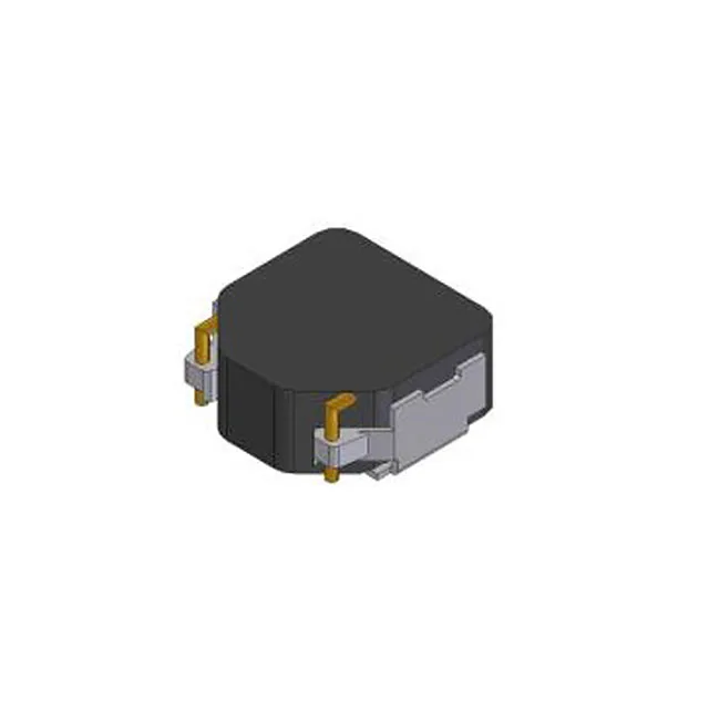
NRND — last-time-buy window for existing designs
The DFEG7030D-1R5M=P3: This means the part remains orderable for existing BOM positions, but Murata does not intend it for new project qualifications. For a production line already qualified on this 1.5 µH shielded inductor, the NRND status is a flag to review the BOM life and secure last-time-buy quantities if the program runs beyond the next 12–18 months.
AEC-Q200 — the automotive reliability baseline
Rated AEC-Q200, the part has passed the full stress-test suite for passive components in automotive electronics: thermal shock, humidity bias, mechanical shock, vibration, and solderability. This qualification is the minimum entry gate for under-hood, transmission, and chassis-mounted power supplies. A 12 V to 3.3 V buck converter in an engine-control unit sees 105°C ambient on a hot day; this inductor's core material and winding insulation are rated for that continuous exposure.
7.6 A rated, 9.7 A saturation — the usable current ceiling
The 7.6 A continuous current rating is the thermal limit at which the inductor's self-heating stays within the 40°C rise envelope. The 9.7 A saturation current (Isat) is the point where the iron-powder core begins to lose inductance — typically a 10% drop. In a buck converter, the peak inductor current during a load transient or start-up must stay below Isat to avoid a hard saturation that sends current spikes through the switching FET. With a 15 mOhm max DCR, the conduction loss at 7.6 A is I²R = 0.87 W. In a 7.00 mm x 6.60 mm x 3.00 mm surface-mount package, that heat is conducted through the PCB copper planes — a 2-ounce copper pour under the part keeps the temperature rise within the 40°C spec.
Shielded iron-powder core — EMI and frequency response
The shielded construction contains the magnetic flux within the core, reducing radiated EMI that could couple into nearby signal traces or wireless receivers. Iron-powder material offers lower core loss than ferrite at switching frequencies above 200 kHz, making this inductor suited for 300–500 kHz DC-DC converters where ferrite cores would run hotter. Inductance is tested at 100 kHz, the standard frequency for power inductor characterization. The ±20% tolerance is typical for shielded power inductors in this class — the saturation current and DCR are the tighter design constraints.