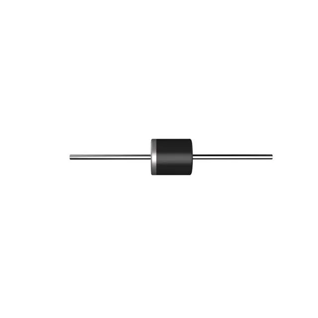
What the 5KP100A-TP is and where it protects
Its 100 V reverse standoff voltage sets the working rail it guards — the clamping ceiling of 162 V defines what reaches the downstream circuitry during a surge event.
What the standoff, breakdown, and clamping ratings mean
The 100 V reverse standoff is the continuous working voltage — the rail the diode watches without conducting. Breakdown kicks in at 111 V minimum, which means the suppressor activates before the downstream IC sees destructive stress. At peak pulse current the clamping voltage climbs to 162 V maximum, so the downstream circuit must tolerate 162 V during the event, not 100 V. For a board designer, the 162 V clamping ceiling is the number that sizes the downstream IC's abs-max margin. A 100 V rail protected by this diode sees 162 V briefly during a surge — the protected device must survive that spike or additional input filtering is needed.
R-6 axial package and through-hole assembly
The R-6 axial package mounts through-hole into a PCB — the through-hole terminations give a robust mechanical joint under vibration compared to SMD alternatives. Soldering follows a standard wave or hand-profile for axial leaded parts; no precision pad alignment is needed, which simplifies board assembly for a high-power suppression component. The -55 °C to 175 °C junction temperature rating reflects the 5 kW peak pulse capability — the die must survive the thermal excursion during a transient event without exceeding Tj-max.
Sourcing and production status
The 5KP100A-TP is listed as Active by Micro Commercial Co — this part is in normal production and suitable for new designs. The base product number 5KP covers a range of standoff voltages in the same package — confirming the exact 100 V variant is required for the BOM position, since the family shares the same footprint but different clamping characteristics.