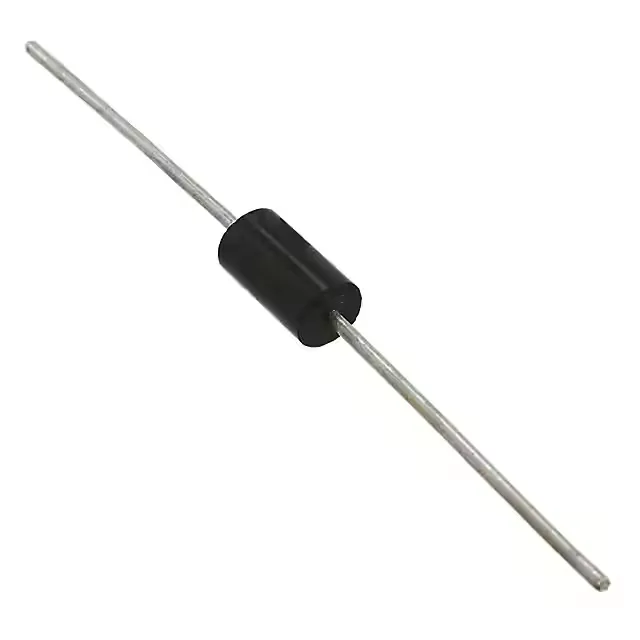
1500 W peak pulse — what it means for your protection rail
The 1.5KE82A-TP: That 1500 W figure is the peak power it can dissipate for a 1 ms/10 µs waveform per the 8/20 µs or 10/1000 µs industry standard — the actual energy-handling capability scales with pulse duration. For a 48 V or 72 V DC bus, the 70.1 V reverse standoff voltage means the diode stays out of the circuit during normal operation and only starts conducting when the line exceeds that threshold. The 77.9 V minimum breakdown voltage is where clamping begins; the 113 V maximum clamping voltage at rated current is the worst-case voltage the downstream circuitry sees. If your protected device has a 100 V absolute maximum rating, this TVS holds the transient below that ceiling with margin.
Through-hole axial — board-fit and thermal path
The DO-201AE axial package is a through-hole form factor with a 0.052-inch (1.3 mm) diameter lead. It wave-solders into a 0.040-inch plated hole on a standard 1.6 mm PCB. The lead frame and body are sized to conduct the 1500 W pulse into the board copper — the thermal path runs through the lead-to-pad solder joint, so adequate pad area and a 2 oz copper pour on the cathode side improve clamping performance under repetitive surge. The upper end covers under-hood automotive ambient and industrial cabinet heat soak; the lower end suits outdoor telecom cabinets in cold climates. The junction itself is the hot spot during a pulse — the 175°C limit is the die temperature, not the case temperature, so the device self-heats during a surge and recovers between events.