15 µF at 50 V — where this capacitance-voltage pair lands
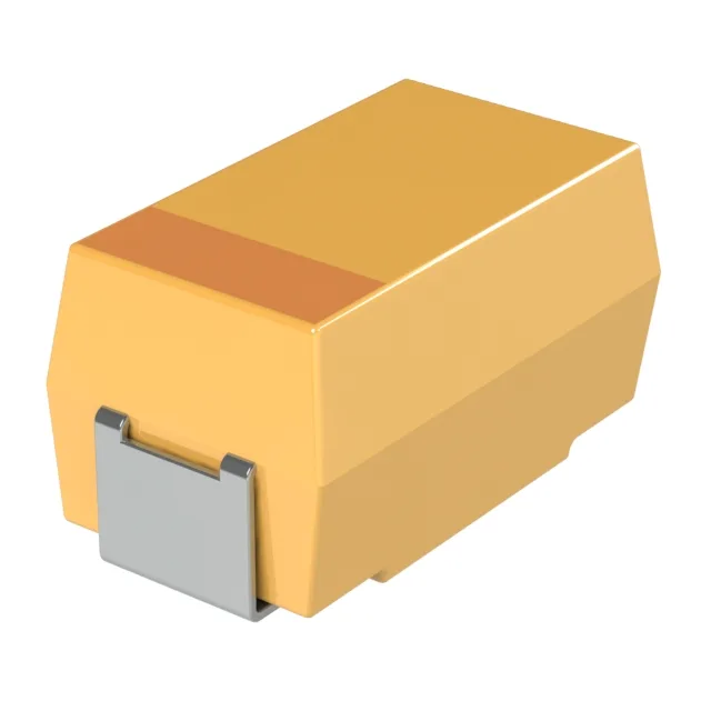
The TPSE156M050S0250: That capacitance-voltage combination is uncommon — most 50 V tantalums top out around 10 µF in the 2917 case, so this part fills a gap for bulk decoupling on a 48 V or 24 V rail where you need more than 10 µF but cannot fit a higher-voltage ceramic or a larger case. The 250 mOhm ESR is the figure that governs ripple-current handling and self-heating. At 15 µF and 50 V, the ripple current rating is roughly 1.2 A RMS at 100 kHz — enough for a switching regulator output filter but not for high-ripple bulk storage. The ESR also sets the impedance floor at resonance: 250 mOhm at ~58 kHz, which is typical for a tantalum of this size and voltage.
Case size, footprint, and board-fit
The footprint matches the standard EIA-7343 land pattern — the same pad layout used by most 2917 tantalums from KEMET, Vishay, and other suppliers. No board respin needed if you are swapping in a 2917 position. Molded construction means the anode and cathode terminations are encapsulated in epoxy rather than a conformal coat. This gives better mechanical protection during pick-and-place and reflow, and the flat top surface is compatible with vacuum nozzles. The molded case also provides a consistent standoff height for solder-joint inspection.
Temperature range and derating
Rated for -55°C to 125°C, this capacitor is qualified for the full industrial temperature range and the lower end of automotive under-hood environments. Tantalum capacitors require voltage derating above 85°C — at 125°C the applied voltage should not exceed 2/3 of the rated 50 V, so about 33 V maximum. This is standard practice for all MnO2 tantalums and is not specific to this part.
Active lifecycle — no LTB pressure
Sourced through independent distribution channels.