What the 30V standoff and 48.4V clamping mean for your protection circuit
The 1.5SMCJ30A-AQ clamps at 48.4 V maximum when a transient drives current through the device — the downstream circuit sees no more than 48.4 V regardless of the surge amplitude, as long as the waveform stays within the 10/1000 µs peak-pulse rating. That 30 V reverse standoff is the working voltage the TVS sees in normal operation; it must stay below 30 V to avoid conduction leakage in the unpowered state. The 31 A peak pulse current tells you the clamping action must divert that current safely to ground — size the upstream impedance and PCB trace accordingly so the clamp does not become the fault path.
The 1.5 kW peak-pulse rating at 10/1000 µs is sized for the load-dump and inductive-spike transient profile found in 12 V automotive systems. If the board runs near 150 °C TJ continuously, the clamping voltage will track higher per the datasheet temperature coefficient, so budget headroom accordingly.
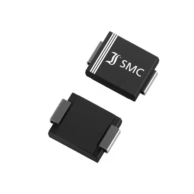
DO-214AB SMC — surface-mount board integration
The DO-214AB (SMC) package with strip packaging ships without reel or cut-tape convolutions — the tape width and peel angle matter for high-speed pick-and-place. The cathode bar on the SMC body aligns with the polarity mark on the reel; verify the placement head vacuums the package centrally to avoid tombstoning on reflow. Land pattern follows the JEDEC DO-214AB footprint — the cathode pad extends under the body for thermal relief, not just electrical connection.