10V standoff, 17V clamp ceiling — what the clamping specs mean
The 1.5SMCJ10A-AQ: The 1.7× clamping ratio means downstream bus protection must tolerate the clamped level, not the raw transient amplitude. Minimum breakdown of 11.1 V gives 1.1 V of headroom above the 10 V standoff — tight enough that this part is not a dual-purpose Zener reference; it is a clamp-first device where the standoff rating, not the Zener nominal, drives the circuit design.
The 88.2 A peak pulse current flows through the clamping path — PCB trace width and via thermal capacity must be sized to carry this current for the duration of the event without opening the ground plane. Only one unidirectional channel is on the die — this protects the positive rail against transients; it does not clamp negative swings, so a bidirectional protection scheme requires a second device oriented in the opposite polarity.
The 150°C maximum junction rating covers the engine-compartment temperature band. In an under-hood enclosure with limited airflow, the designer must still calculate the board-level thermal resistance from junction to ambient — the 150°C ceiling is the thermal budget, not the operating ambient. Listed applications flag automotive — the thermal cycling demand on a TVS in the engine bay is more severe than the module average. Verify that the Diotec automotive grade screening aligns with the AEC-Q101 test envelope if the end application requires AEC-CAP compliance.
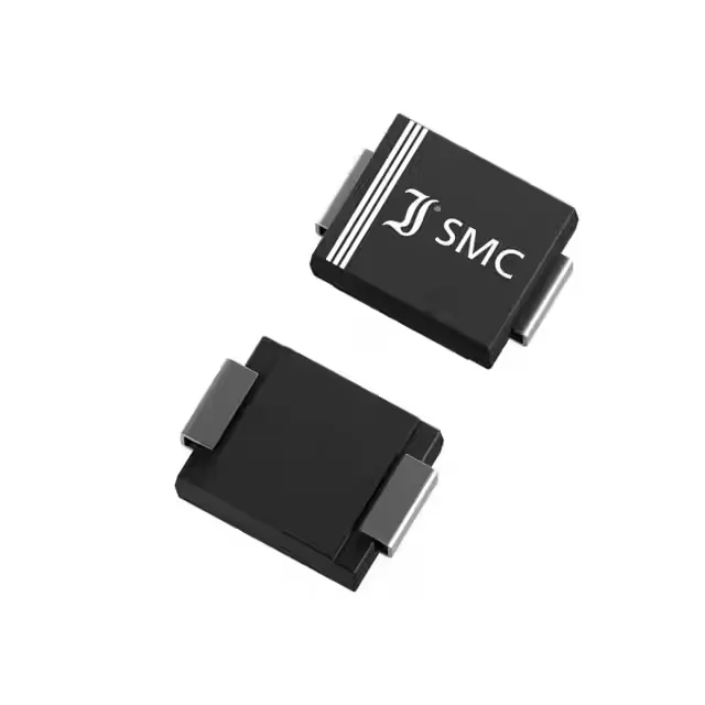
SMC/DO-214AB footprint — automotive PCB layout
The SMC (DO-214AB) body is the standard large-body TVS footprint on automotive ECUs — the cathode band is the polarity indicator. The strip packaging suggests reel-cut or loose-reel delivery; confirm the taping orientation matches the pick-and-place system. Surface-mount termination on a copper pad requires attention to solder-joint integrity under thermal cycling — the DO-214AB heel fillet carries mechanical stress when the board flexes. IPC-A-610 Class 3 assembly will govern the acceptance criteria for an automotive environment.