What the 30.8 V standoff and 49.9 V clamp mean for rail protection
The 30.8 V reverse standoff voltage (V_RWM) sets the maximum DC operating voltage the protected rail can carry without the diode conducting leakage current — a 24 V nominal rail with 20 % tolerance sits safely under this ceiling. When a transient exceeds the 34.2 V minimum breakdown voltage (V_BR), the device avalanches and clamps at 49.9 V maximum while shunting 12 A peak pulse current. The 49.9 V clamp is the voltage the downstream circuitry must survive; a 36 V-rated DC-DC converter or 40 V-rated MOSFET has no margin here, so the P6KE36A-T suits 24 V rails where the load is rated for 50 V or more.
Package and board-fit: DO-15 axial, through-hole
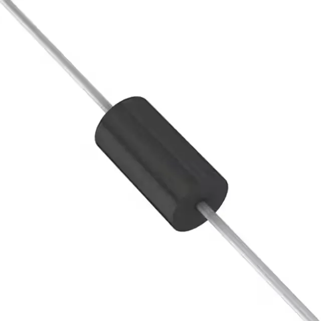
Supplied in a DO-204AC (DO-15) axial-lead through-hole package. The body diameter is approximately 3.6 mm with 25.4 mm lead spacing — fits standard 0.100-inch pitch prototyping boards and existing P6KE-series PCB footprints. The axial leads are solderable in wave or hand-solder processes; no special reflow profile needed. The 175 °C T_J max means the device does not thermally derate significantly until ambient exceeds 125 °C in still air, assuming the PCB copper area carries the heat from repetitive pulses.
Lifecycle status and sourcing approach
Diodes Incorporated lists the P6KE36A-T as Obsolete. Sourcing is through independent distribution channels — inventory is lot-specific, with date-code and quantity confirmed at RFQ. The axial DO-15 package and P6KE series footprint are standard enough that a cross-reference to an active competitor's part may be possible, but no pin-compatible Diodes replacement is published.