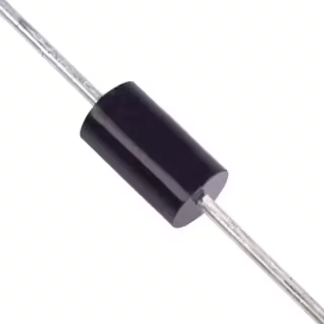
1500 W peak pulse, 256 V standoff — the clamp that defines the rail
The 1.5KE300CA-B: The 414 V clamp ceiling is the number that matters for rail protection — if the protected bus sees a transient that drives the TVS into avalanche, the voltage across the diode will not exceed 414 V, regardless of the surge current up to the 5 A peak rating. This sets the withstand requirement for downstream components.
Obsolete — sourced against the BOM through independent channels
Diodes Incorporated lists the 1.5KE300CA-B as Obsolete. The DO-201AA (DO-27) axial package is a through-hole footprint common in power-supply and industrial input-protection designs. The Bulk packaging suits low-volume production runs and prototyping where tape-and-reel is not required.
285 V breakdown, 414 V clamp — the numbers that decide the design margin
The minimum breakdown voltage of 285 V means the TVS does not conduct at the 256 V standoff rail — no leakage current penalty during normal operation. The maximum clamping voltage of 414 V defines the peak voltage the protected load must survive; a downstream DC-DC converter or capacitor bank rated for 450 V has headroom, while a 400 V-rated part does not. The single bidirectional channel protects one rail in either polarity, simplifying board layout for AC or floating DC lines.