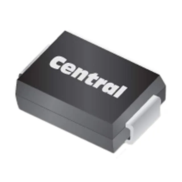
The 1.5SMC8.2CA TR13 PBFREE: The reverse standoff of 7.02 V typ defines the working voltage the protected rail can sit at continuously without the TVS drawing significant leakage — it is a steady-state clamp-off level, not a trip point. The minimum breakdown of 7.79 V is where the Zener characteristic kicks in and the device begins conducting. The 7.79 V breakdown minimum sitting only ~770 mV above the 7.02 V standoff typ is a tight design window. In a 7 V rail protection scheme the part is correctly sized; but on a 6 V rail the standoff headroom is generous and the breakdown is still above the rail, so no unwanted clamping during normal operation. If the target application carries shorter, sharper spikes (ESD human-body model at 8/20 µs), the peak let-through energy is lower and the clamping voltage sits closer to the Vbr region, not the 12.1 V spec ceiling.
SMC footprint and thermal housekeeping
The DO-214AB (SMC) package thermal path runs through the cathode tab solder joint to the PCB copper. Pb-free finish on the tab and the tape-and-reel packaging confirm this part is assembled on standard SMT lines with Pb-free profile reflow — no special handling required.