Clamping voltage and standoff — what the two ratings mean
The 1.5SMC62CA TR13 PBFREE: The 85V clamping voltage at 17.7A peak pulse (10/1000 µs) is the actual transient-suppression ceiling — this is what the downstream circuit sees when the TVS fires. The 53V reverse standoff rating is the working voltage the TVS tolerates without conduction in normal operation, so the circuit can sit below that level indefinitely without the TVS drawing leakage current. With 1.5 kW peak pulse power rated into the 85V clamp, the part absorbs the surge energy and clamps hard — this makes it suitable as the primary clamping element on signal lines and low-power rails where you need a defined let-through ceiling without relying on upstream series impedance.
DO-214AB SMC package and thermal margins
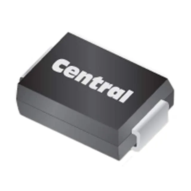
The DO-214AB (SMC) package gives the tab area needed to dissipate the short-duration surge energy without the junction exceeding 150°C. Surface-mount termination and the SMC package footprint are the standard land-pattern for most commercial SMPS and I/O protection zones — the copper pad under the device on the PCB is the primary thermal path for surge heat dissipation.
Bidirectional, single-channel Zener-class TVS
A single bidirectional channel means this is a back-to-back Zener structure — it clamps both polarities without requiring separate unidirectional devices or a diode bridge. This simplifies the protection scheme on AC-coupled signal lines or bidirectional data buses. Listed as general-purpose application — the peak pulse rating of 1.5 kW positions it between the 200-500 W consumer TVS range and the 3-5 kW industrial-grade devices. It covers the mid-range transient suppression slot common in power supplies, communication equipment, and instrumentation protection zones.