What the clamping ratings mean
The 1.5SMC6.8CA TR13 PBFREE: A 5.8 V standoff with a 10.5 V clamping ceiling at 143 A peak pulse means the suppressor clamps a transient to safe levels before the downstream circuit sees the spike — the 3.7 V differential between standoff and clamping is the absorbed headroom at the rated surge current. For a 24 VDC rail, the standoff sits comfortably below the working voltage, leaving margin for the clamping event without false triggering under normal operation. The 1.5 kW peak pulse rating (1/1000 µs waveform) defines the energy the device can absorb once — a single surge event. Repeated transients or longer-duration events derate the available peak; the junction temperature ceiling of 150°C is the hard stop on how hot the die can run before the clamping voltage drifts upward.
Package and thermal integration
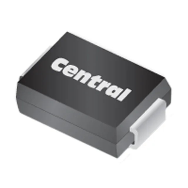
The DO-214AB (SMC) package lands on a standard SMA/SMB pad footprint — most layouts can swap between series without a board respin. The cathode band marks the polarity on the single-directional orientation; bidirectional variants clamp symmetrically on both polarities, which matters for AC line or signal bus protection. Operating junction temperature runs to 150°C, so the SMC's thermal pad plane determines how quickly the die temperature settles after a clamping event. A board with adequate copper area under the cathode tab keeps the thermal path low — the datasheet curve will show the required pad size for the target peak pulse count.
Listed as Active by Central Semiconductor Corp — ordered by the BOM line, availability and lead time confirmed at quote time against the RFQ.