What the clamping specs mean for your protection circuit
The 1.5SMC6.8A TR13 PBFREE: A 5.8 V reverse standoff gives the normal operating margin; the 6.45 V minimum breakdown is where the TVS begins conducting. For a 5 V rail, this window gives roughly 0.8 V of headroom before the suppressor activates, which is tight — confirm the downstream absolute maximum rating can survive a 10.5 V clamping spike if the standoff is ever exceeded. The actual surge energy your application sees depends on the source impedance and pulse duration; a longer or higher-energy event derates the device's capability below this headline number.
DO-214AB package and thermal integration
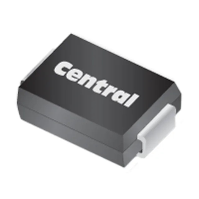
The DO-214AB (SMC) is the standard package for 1.5 kW TVS diodes — the wide metal slug on the cathode tab conducts heat away from the junction. Junction temperature is rated to 150 °C, with a storage range extending down to -65 °C, so the device handles both the surge self-heating and cold-environment operation. The supplier device package is listed as SMC — confirm the land pattern matches the DO-214AB footprint on your board; the tab is typically electrically common with the cathode. Surface-mount termination means this is a pick-and-place part — the Tape & Reel packaging supports standard SMT assembly flow. The TR13 reel designator refers to the reel diameter; confirm the carrier tape width and hub size against your feeder specification before programming the placement head.