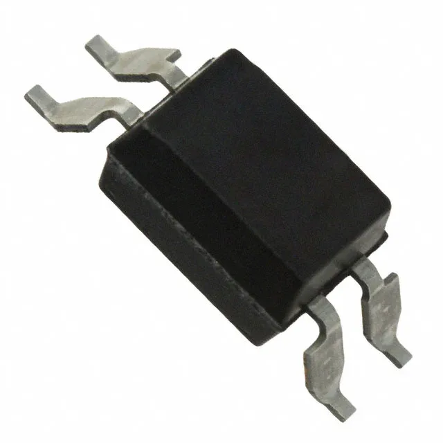
Renesas Electronics PS2561DL2-1Y-F3-A — Optoisolators

PS2561DL2-1Y-F3-A NEPOC Optocoupler, 5000Vrms, 4-SMD

MPNPS2561DL2-1Y-F3-A
End of Life

Renesas / NEPOC PS2561DL2-1Y-F3-A single-channel transistor-output optocoupler, 5000Vrms isolation, 50%–400% CTR at 5mA, 80V output, 3µs/5µs rise/fall, -55°C to 110°C, 4-SMD Gull Wing, Tape & Reel.

$0.31108Ref. price · indicative, final on quote
Packaging4-SMD, Gull Wing
StockContact for availability
MOQ1 pcs
  • 100% new & originalTraceable channels only — no refurbs, no pulls, no remarked parts.
  • Date & lot codes on quoteStated per line before you commit; label photos on request.
  • MSL-compliant ESD packingMoisture-sealed bags with indicator cards; reels photo-verified.
  • PayPal buyer protectionPay by T/T, PayPal or Payoneer — card payments covered end to end.

Specifications

PS2561DL2-1Y-F3-A Technical Specifications
ParameterValue
SeriesNEPOC
Input typeDC
Output typeTransistor
Mounting typeSurface Mount
Voltage - isolation5000Vrms
Voltage - output80V
Voltage - forward (Vf)1.2V
Current - output (Channel)50mA
Current transfer ratio400% @ 5mA
Current - DC forward (If)40 mA
Operating temperature-55°C ~ 110°C
PackageTape & Reel (TR)
Case4-SMD, Gull Wing
Number of channels1
Vce saturation300mV
Rise (Fall time)3µs, 5µs

Product details

5000Vrms isolation in a 4-SMD gull-wing package

The Renesas NEPOC PS2561DL2-1Y-F3-A is a single-channel transistor-output optocoupler designed for galvanic isolation in industrial and power-conversion interfaces. Its 5000Vrms isolation rating suits reinforced insulation requirements for mains-voltage separation in PLC digital inputs, motor-drive feedback, and AC-line monitoring circuits. The 4-SMD gull-wing package supports automated surface-mount assembly and visual inspection of solder joints. Key parametrics include a current transfer ratio (CTR) range of 50% to 400% at 5mA forward current, a maximum Vce saturation of 300mV, and an output transistor rated to 80V and 50mA continuous. Rise and fall times are 3µs and 5µs typical, limiting the practical switching rate to low-speed digital signals such as 50/60 Hz line sync, relay coil feedback, or slow PLC input sampling. The 1.2V typical forward voltage and 40mA maximum forward current are standard for 3.3V or 5V logic-driven LEDs with a series resistor.

For dual-sourcing resilience, the PS2801C-4-V-A is a four-channel variant with 2500Vrms isolation and similar transistor-output characteristics, though it is not a pin-compatible drop-in due to channel count and package differences.

CTR range and drive margin for the BOM

The 50% minimum CTR at 5mA forward current means the output transistor can sink at least half the LED current, which directly sets the pull-up resistor value on the output side. A 5mA LED drive with a 10kΩ pull-up to 5V yields about 0.5mA base drive — enough to saturate the output below 300mV for a logic-low signal. The 400% maximum CTR gives headroom for LED aging or temperature derating; designs should verify the minimum CTR at the lowest expected operating temperature and LED current. At 3.3V logic, the 1.2V Vf leaves about 2.1V across the current-limiting resistor. A 390Ω resistor sets the forward current near 5mA, keeping the LED within the 40mA absolute maximum and maintaining the CTR within the specified test condition. The 80V output rating allows direct interface to 24V industrial logic or 48V telecom rails without an external level shifter.

Frequently asked questions

What is the price of PS2561DL2-1Y-F3-A?

Submit an RFQ for current per-unit pricing based on your target volume and delivery schedule.

Is PS2561DL2-1Y-F3-A available via RFQ confirmation?

Availability is verified at quote time.

Does PS2561DL2-1Y-F3-A work with 3.3V logic?

Yes. The 1.2V typical forward voltage allows direct drive from a 3.3V GPIO through a series resistor. At 3.3V supply, a 390Ω resistor sets the LED current near 5mA, which is the test condition for the 50%–400% CTR range. The output transistor saturates below 300mV, providing a clean logic-low to a 3.3V receiver.

What is the maximum switching speed of PS2561DL2-1Y-F3-A?

Typical rise and fall times are 3µs and 5µs respectively, which limits practical data rates to roughly 100 kbps or less. This part is intended for low-speed isolation of DC signals, 50/60 Hz line sync, relay status, or slow digital inputs — not for high-speed communication like SPI or CAN.