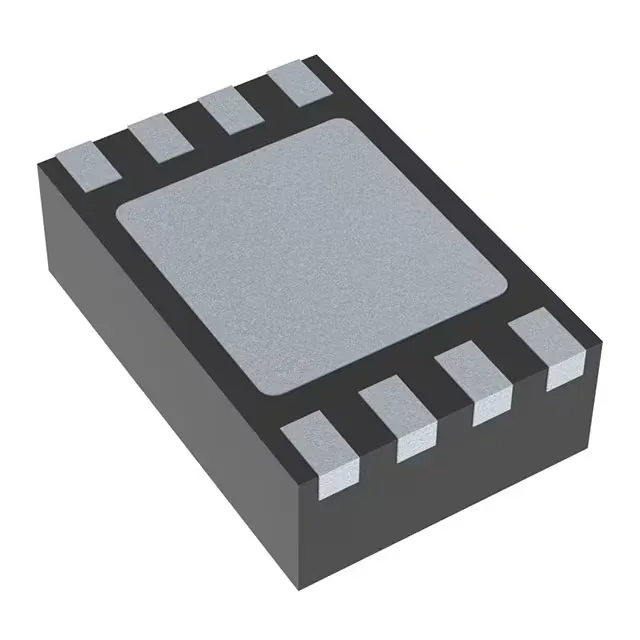
The ISL6840IRZ-T: RoHS3 compliant, so it passes the EU material restriction threshold for lead, mercury, and the other five substances without an exemption.
2 MHz switching shrinks the magnetics
The oscillator runs up to 2 MHz — at that frequency a boost inductor or flyback transformer can use a smaller core and fewer turns, saving board area. 96 % max duty cycle means the controller can hold the switch on for nearly the whole period, useful when the input-to-output step-up ratio is large — for example, boosting a 5 V rail to 48 V in a single stage without a cascaded converter. Synchronous rectification is built in — the controller drives an external low-side FET for the rectifier, replacing a Schottky diode.
Boost or flyback — one controller, two topologies
The ISL6840IRZ-T is a current-mode PWM controller that handles both boost and flyback topologies. Current-mode control gives cycle-by-cycle current limiting and simpler loop compensation than voltage-mode — the slope-compensation pin is available for duty cycles above 50 % to prevent subharmonic oscillation. Output configuration is positive and isolation-capable — in a flyback design the transformer provides galvanic isolation, so the secondary side can float relative to the primary ground. The controller itself sits on the primary side and drives the primary FET. Supply range is 7.5 V to 14 V — typical for a bias winding on the transformer or a regulated auxiliary rail. The undervoltage lockout threshold keeps the controller off until the supply is high enough to drive the FET gate fully.
8-DFN exposed-pad — thermal and layout notes
The 8-DFN package measures 2 mm × 3 mm with an exposed pad on the bottom. The datasheet's recommended footprint includes a thermal via array under the pad. That covers most telecom, industrial, and lighting applications but does not meet AEC-Q100 automotive requirements. For under-hood or cabin electronics, a different grade would be needed.