Active production — sourcing for the BOM line
The ISL6208CBZ-T: ROHS3 compliant — no restricted-substance exemptions that would trigger a future revision or require a waiver for European-market builds.
Half-bridge driver — 2 A peak into synchronous N-channel FETs
Driven configuration is half-bridge, channel type synchronous, gate type N-channel MOSFET — the standard topology for a synchronous buck converter's high-side and low-side FETs. Peak output current is 2 A source and 2 A sink, enough to charge and discharge the gate capacitance of a medium-power MOSFET in the 10–30 nC range without excessive switching loss. Non-inverting input means the driver output follows the logic input without polarity inversion — the PWM controller's signal goes straight to the driver without an external inverter.
Supply rail and bootstrap — 5 V part with 33 V high-side headroom
High-side bootstrap voltage maximum is 33 V, meaning the floating driver supply can ride up to 33 V above the switch node — adequate for a 24 V input rail with margin for transients.
Switching speed and package — 8 ns edges in an 8-SOIC
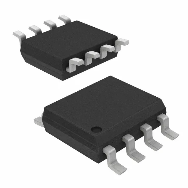
Typical rise and fall times are 8 ns each — fast enough for switching frequencies above 500 kHz without the dead-time penalty eating into duty cycle, but fast enough that the gate-drive loop inductance must be kept under 10 nH to avoid ringing. Package is 8-SOIC (0.154" body width, 3.90 mm), supplier device package 8-SOIC — standard footprint with no exposed thermal pad, so junction-to-ambient thermal resistance depends on the PCB copper area under the part.