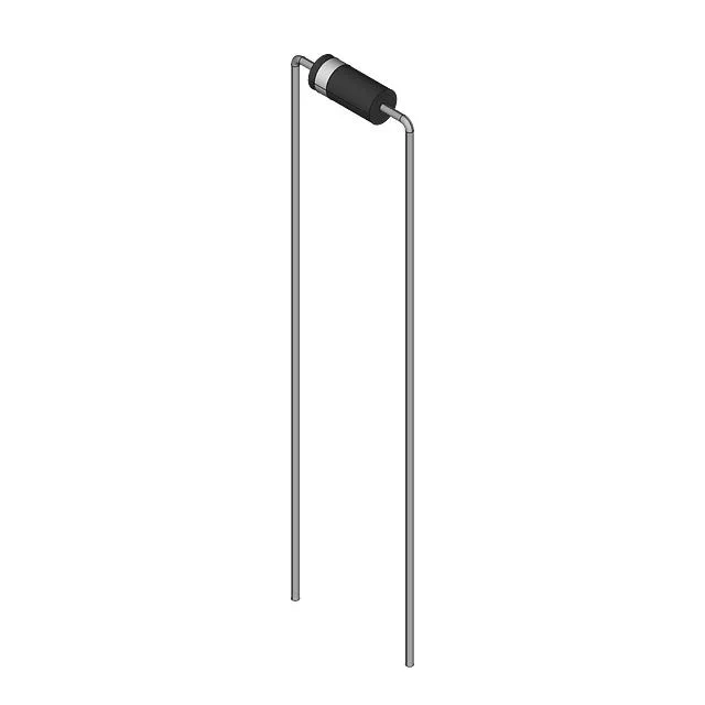
Renesas Electronics HZ12BP-E

HZ12BP-E Zener Diode, 12V, 1W, DO-41, ±5% Tolerance

MPNHZ12BP-E
End of Life

HZ-P series Zener diode, 12 V nominal, 1 W power dissipation, ±5% tolerance, DO-204AL (DO-41) axial through-hole package, bulk.

$0.36Ref. price · indicative, final on quote
PackagingDO-204AL, DO-41, Axial
RoHSNot applicable
SeriesHZ-P
Independent supplier — new & surplus stockAuthenticity-screened · ESD-safe packingListing updated Jul 2026

Specifications

HZ12BP-E specifications
ParameterValue
SeriesHZ-P
MountingThrough Hole
Voltage - zener (Nom)12 V
Current - reverse leakage @ vr10 µA @ 9 V
Power - max1 W
Operating temperature175°C (TJ)
PackageBulk
Tolerance±5%
CaseDO-204AL, DO-41, Axial
Impedance (Max)8 Ohms

Product details

The HZ12BP-E is a 12 V Zener diode from the HZ-P series, rated for 1 W continuous power dissipation in a DO-41 axial-lead package. The 12 V nominal voltage with ±5% tolerance covers the typical regulation window for 12 V rails and clamp circuits. The 8 Ohms maximum Zzt impedance means the diode holds regulation reasonably tight under moderate current changes — expect a few tens of millivolts of shift across the operating current range.

Package and mounting — DO-41 axial, through-hole

The DO-41 axial package is the standard for 1 W Zener diodes. The through-hole mounting suits point-to-point wiring, terminal strips, or PCB.

Lifecycle — active, no phase-out signal

Frequently asked questions

What is the equivalent part for HZ12BP-E?

A common cross-shop candidate is the 1N4742A, which is also a 12 V, 1 W Zener in a DO-41 package with ±5% tolerance. The 1N4742A is a JEDEC-registered device and is widely second-sourced. Verify the specific impedance and leakage characteristics against your circuit's requirements before substituting.

How do I test HZ12BP-E with a multimeter?

Use the diode test range: forward bias should read roughly 0.6–0.8 V; reverse bias should show open circuit (OL) at low test voltage. For a functional Zener voltage check, apply a current-limited supply (e.g., 10–20 mA through a resistor) and measure the voltage across the diode — it should read 12 V ±5%.