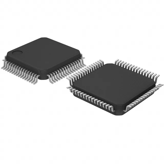
The NXP LPC1517JBD64Y is a 32-bit ARM Cortex-M3 MCU running at 72 MHz, with 64 KB of Flash program memory, 12 KB SRAM, and 4 KB on-chip EEPROM. It integrates CANbus, I²C, SPI, and UART/USART connectivity, 46 general-purpose I/Os, a 24-channel 12-bit ADC, and internal oscillator. The part is specified over the -40°C to 105°C industrial temperature range and operates from a 2.4 V to 3.6 V supply. Typical applications include industrial control nodes, CAN-based sensor hubs, and motor-control interfaces where the on-chip EEPROM eliminates an external serial memory device.
72 MHz core — headroom for control loops
The 72 MHz clock rate on this Cortex-M3 core provides enough throughput for control loops with CAN messaging.
The 105°C upper limit means it can sit near a power stage or in a sealed enclosure without forced air, as long as the local ambient stays under that ceiling. The on-chip brown-out detect and POR help maintain reset integrity across supply dips common in noisy industrial environments.
On-chip EEPROM — one fewer external part
The 4 KB EEPROM block stores calibration constants, node IDs, and fault logs without a separate serial EEPROM footprint.