Active production and BOM-fit check
The LQH32DZ100K53L: The 10 µH inductance at 450 mA DC rating sets the current ceiling for the power rail or signal path this inductor serves. At the rated current, the 390 mOhm max DCR produces an I²R loss of roughly 79 mW — a figure that stays within the 105°C operating limit when the ambient is below 85°C and the board has moderate copper pour.
AEC-Q200 qualification and deployment envelope
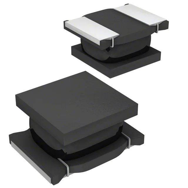
The unshielded drum-core construction radiates the magnetic field — the layout must keep sensitive analog traces, low-level sensor lines, or RF signal paths at least 3 mm from the inductor body to avoid coupling. For a DC-DC converter input filter, the radiated field is usually not a concern; for a precision ADC reference filter, it is.
Self-resonant frequency and frequency-domain fit
The 26 MHz self-resonant frequency (SRF) marks the point where the inductor's parasitic capacitance cancels the inductance — above 26 MHz the component behaves capacitively and no longer provides inductive impedance. For a buck converter switching at 2 MHz, the SRF is well above the fundamental and the first few harmonics, so the inductor filters effectively. For a 10 MHz switching regulator or a filter above 10 MHz, the margin narrows and the effective inductance rolls off. Inductance is tested at 1 MHz, which is the standard test frequency for the 10 µH value in the 1210 package. The ±10% tolerance band covers the full operating temperature range and DC bias condition up to the rated current.
Package and reflow integration
The ferrite core and wirewound construction are compatible with standard lead-free reflow profiles (peak 260°C, 30 seconds above 255°C).