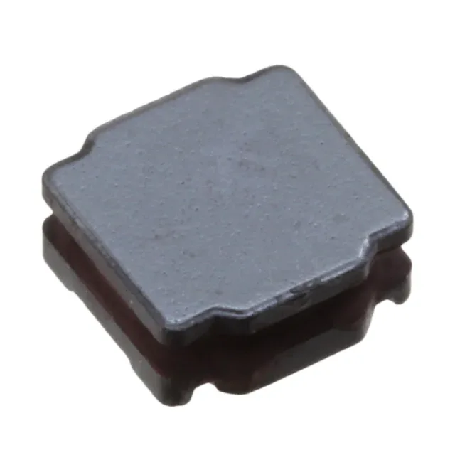
Murata Electronics LQH2MPZ680MGRL — Inductors & Chokes

Murata LQH2MPZ680MGRL 68 µH Shielded Power Inductor, 160 mA

MPNLQH2MPZ680MGRL
Active

Murata Electronics LQH2 series, Drum Core Wirewound Inductor, 68 µH, ±20%, Shielded, 160 mA, 8.04 Ohm DCR, 0806 (2016 Metric), AEC-Q200.

$0.3300Ref. price · indicative, final on quote
Sourced new & surplus through independent channelsAuthenticity-screened · ESD-safe packingListing updated Aug 2026

Specifications

LQH2MPZ680MGRL specifications
ParameterValue
TypeDrum Core, Wirewound
SeriesLQH2
MountingSurface Mount
Current rating160 mA
Current - saturation230mA
Frequency - self resonant7MHz
Inductance frequency - test1 MHz
Operating temperature-40°C ~ 105°C
Material - coreFerrite
Size (Dimension)0.079\" L x 0.063\" W (2.00mm x 1.60mm)
Height - seated0.037\" (0.95mm)
PackageTape & Reel (TR) Cut Tape (CT)
RatingsAEC-Q200
ShieldingShielded
Tolerance±20%
Inductance68 µH
Case0806 (2016 Metric)
DC resistance8.04Ohm Max

Product details

68 µH, 160 mA — the sizing decision for an automotive DC-DC filter

The LQH2MPZ680MGRL is a 68 µH shielded wirewound inductor from Murata's LQH2 series, rated for 160 mA continuous DC with a maximum DC resistance of 8.04 Ohm. The 230 mA saturation current (Isat) is the hard ceiling: the inductance holds its value up to this current, then the ferrite core saturates and the inductance drops sharply. The 160 mA DC rating already includes a derating margin below saturation, so the practical operating limit is the DC rating, not the saturation number.

AEC-Q200 qualification and the 105°C ceiling

The ferrite core material and shielded construction keep the magnetic field contained within the 0806 package — important when the inductor sits next to a sensitive ADC reference or a CAN transceiver on the same board layer.

Self-resonant frequency — where the part stops being an inductor

The self-resonant frequency (SRF) is 7 MHz. Below this frequency the component behaves as an inductor with the rated 68 µH; at and above 7 MHz the parasitic winding capacitance dominates and the impedance becomes capacitive. For a buck converter switching at 2 MHz, the SRF gives plenty of headroom — the inductor's impedance stays inductive at the switching fundamental and its first few harmonics. The low profile keeps it under a 1.0 mm clearance on a two-layer board.

Frequently asked questions

What is the DC resistance and how does it affect the design?

The maximum DC resistance is 8.04 Ohm. At the rated 160 mA DC current, the I²R loss is about 0.21 W — negligible for the 0806 package's power dissipation capability, but the DCR contributes to the output voltage drop in a filter application. For a 5 V rail drawing 100 mA, the DCR drop is 0.8 V, so the post-inductor voltage is 4.2 V — factor this into the regulator's feedback sense point.

What is the tolerance and how is inductance tested?

The inductance tolerance is ±20%, tested at 1 MHz. A 68 µH part can measure anywhere from 54.4 µH to 81.6 µH at the test frequency. The 1 MHz test frequency is standard for power inductors in this value range — it avoids the SRF region (7 MHz) and gives a clean inductance reading.