Obsolete — sourcing for existing BOM lines
Murata lists the DFEG12060D-6R8M=P3 as Obsolete — the manufacturer no longer produces this order code.
6.8 µH, 9 A — what the ratings mean for your converter
6.8 µH at 100 kHz test frequency is the nominal inductance before DC bias. The iron powder core holds inductance under load better than a ferrite core of the same volume — the 11 A saturation current is the hard limit where inductance drops by 30 %, and it sits 2 A above the 9 A continuous rating, giving headroom for transient spikes without core collapse. 14 mOhm max DCR at 9 A produces 1.13 W of I²R loss in the winding — that heat must be conducted through the nonstandard package to the PCB copper. The 125 °C ceiling means the inductor can sit next to a hot MOSFET or a 105 °C ambient without derating the current, provided the board copper pulls the heat away.
AEC-Q200 — what it certifies for the application
The 125 °C max operating temperature aligns with the Grade 1 temperature class — suitable for under-hood or engine-bay modules that see sustained 105 °C ambient.
Shielded construction and board footprint
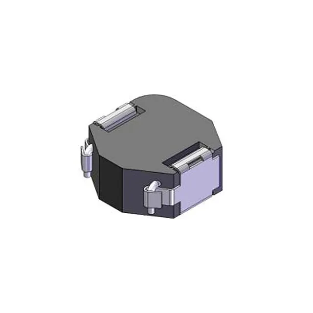
Shielded construction contains the magnetic flux within the core — the fringe field that would couple into a nearby trace or another inductor is suppressed. In a multi-phase buck converter with inductors placed side-by-side, the shielding keeps the mutual inductance low enough that the phases do not cross-couple. The 13.00 mm x 12.60 mm footprint with a 6.00 mm seated height is a nonstandard package — the pad layout is specific to this Murata series. No standard 12 mm x 12 mm or 13 mm x 13 mm footprint matches exactly; the PCB land pattern must follow the Murata drawing for this part.